Chrysler Sebring, Stratus sedan, Sebring Convertible. Manual - part 282
STANDARD PROCEDURE - BASE BRAKE
BLEEDING
NOTE: For bleeding the ABS hydraulic system,
(Refer to 5 - BRAKES - ABS - STANDARD PROCE-
DURE).
CAUTION: Before removing the master cylinder cap,
wipe it clean to prevent dirt and other foreign mat-
ter from dropping into the master cylinder reservoir.
CAUTION: Use only Mopar
T
brake fluid or an equiv-
alent from a fresh, tightly sealed container. Brake
fluid must conform to DOT 3 specifications.
Do not pump the brake pedal at any time while
having a bleeder screw open during the bleeding pro-
cess. This will only increase the amount of air in the
system and make additional bleeding necessary.
Do not allow the master cylinder reservoir to run
out of brake fluid while bleeding the system. An
empty reservoir will allow additional air into the
brake system. Check the fluid level frequently and
add fluid as needed.
The following wheel circuit sequence for bleeding
the brake hydraulic system should be used to ensure
adequate removal of all trapped air from the hydrau-
lic system.
• Left rear wheel
• Right front wheel
• Right rear wheel
• Left front wheel
MANUAL BLEEDING
NOTE: To bleed the brakes manually, the aid of a
helper will be required.
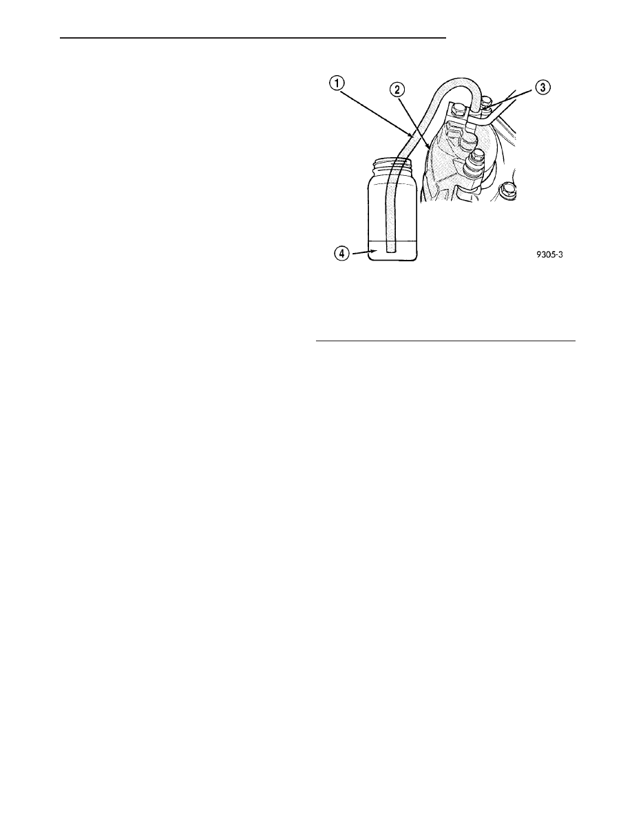
(1) Attach a clear plastic hose to the bleeder screw
and feed the hose into a clear jar containing enough
fresh brake fluid to submerge the end of the hose
(Fig. 1).
(2) Have a helper pump the brake pedal three or
four times and hold it in the down position.
(3) With the pedal in the down position, open the
bleeder screw at least 1 full turn.
(4) Once the brake pedal has dropped, close the
bleeder screw. After the bleeder screw is closed,
release the brake pedal.
(5) Repeat the above steps until all trapped air is
removed from that wheel circuit (usually four or five
times).
(6) Bleed the remaining wheel circuits in the same
manner until all air is removed from the brake sys-
tem. Monitor the fluid level in the master cylinder
reservoir to make sure it does not go dry.
(7) Check the brake pedal travel. If pedal travel is
excessive or has not been improved, some air may
still be trapped in the system. Rebleed the brakes as
necessary.
(8) Test drive the vehicle to verify the brakes are
operating properly and pedal feel is correct.
PRESSURE BLEEDING
NOTE:
Follow
pressure
bleeder
manufacturer’s
instructions for use of pressure bleeding equip-
ment.
Use bleeder tank, Special Tool C-3496-B or equiva-
lent, with master cylinder reservoir adapter, Special
Tool 8224, to pressurize the hydraulic system for
bleeding.
Following the same wheel circuit sequence as pre-
scribed for manual bleeding.
(1) Attach a clear plastic hose to the bleeder screw
and feed the hose into a clear jar containing enough
fresh brake fluid to submerge the end of the hose
(Fig. 1).
(2) Open the bleeder screw at least one full turn or
more to obtain a steady stream of brake fluid.
(3) After approximately 4–8 ounces of fluid have
been bled through the brake circuit and an air-free
flow is maintained in the clear plastic hose and jar,
close the bleeder screw.
(4) Repeat this procedure at all the remaining
bleeder screws.
Fig. 1 Proper Method for Purging Air From Brake
System (Typical)
1 - CLEAR HOSE
2 - BRAKE CALIPER
3 - BLEEDER SCREW
4 - CLEAN BRAKE FLUID
JR
BRAKES - BASE
5 - 3
BRAKES - BASE (Continued)