Chrysler Le Baron, Dodge Dynasty, Plymouth Acclaim. Manual - part 595


  Index      Chrysler     Chrysler Le Baron, Dodge Dynasty, Plymouth Acclaim - service repair manual 1993 year


Search            


Content   ..  593  594  595  596   ..


Chrysler Le Baron, Dodge Dynasty, Plymouth Acclaim. Manual - part 595


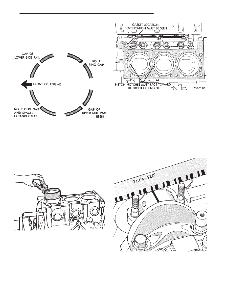
(5) Position piston ring end gaps as shown in (Fig.

13).

(6) Position oil ring expander gap at least 45° from

the side rail gaps but not on the piston pin center or on
the thrust direction. Staggering ring gap is important
for oil control.

INSTALLING PISTON AND CONNECTING ROD AS-
SEMBLY

(1) Before installing pistons and connecting rod as-

semblies into the bore, besure that compression ring
gaps are staggered so that neither is in line with oil
ring rail gap.

(2) Before installing the ring compressor, make sure

the oil ring expander ends are butted and the rail gaps
located as shown in (Fig. 14).

(3) Immerse the piston head and rings in clean

engine oil, slide the ring compressor, over the piston
and tighten with the special wrench. Be sure position
of rings does not change during this operation.

(4) Install connecting rod bolt protectors on rod

bolts. (Fig. 3)

(5) Rotate crankshaft so that the connecting rod

journal is on the center of the cylinder bore. Insert
rod and piston into cylinder bore and guide rod over
the crankshaft journal.

(6) Tap the piston down in cylinder bore, using a

hammer handle. At the same time, guide connecting
rod into position on connecting rod journal.

(7) The notch or groove on top of piston must be

pointing toward front of engine (Fig. 15).

(8) Install rod caps. Install nuts on cleaned and

oiled rod bolts and tighten nuts to 54 N

Im (40 ft. lb.)

Plus 1/4 turn.

Fig. 15 Piston I.D. Notches

Fig. 16 Checking Connecting Rod Bearing

Clearance

Fig. 13 Piston Ring End Gap Position

Fig. 14 Installing Piston

Ä

3.3/3.8L ENGINE

9 - 117

CONNECTING RODS

INSTALLATION OF CONNECTING ROD BEAR-
INGS

Fit all rods on one bank until complete.
The bearing caps are not interchangeable and should

be marked at removal to insure correct assembly.

The bearing shells must be installed with the tangs

inserted into the machined grooves in the rods and
caps. Install cap with the tangs on the same side as the
rod.

Limits of taper or out-of-round on any crankshaft

journals should be held to .025mm (.001 inch). Bear-
ings are available in .025mm (.001 inch), .051mm (.002
inch),.076mm (.003 inch), .254mm (.010 inch) and
.305mm (.012 inch) undersize. Install the bearings
in pairs. Do not use a new bearing half with an
old bearing half. Do not file the rods or bearing
caps.

(1) Follow procedure specified in the Standard Ser-

vice Procedure Section for Measuring Main Bearing
Clearance and Connecting Rod Bearing Clearance
(Fig. 16).

The rod bearing bolts should be examined be-

fore reuse. If the threads are necked down the
bolts should be replaced (Fig. 19).

Necking can be checked by holding a scale or straight

edge against the threads. If all the threads do not
contact the scale the bolt should be replaced.

(2) Before installing the nuts the threads should be

oiled with engine oil.

(3) Install nuts on each bolt finger tight then alter-

nately torque each nut to assemble the cap properly.

(4) Tighten the nuts to 54 N

Im PLUS 1/4 turn (40 ft.

lbs. PLUS 1/4 turn).

(5) Using a feeler gauge, check connecting rod side

clearance (Fig. 17). Refer to (Fig. 18) for specifications.

CRANKSHAFT SERVICE

CRANKSHAFT MAIN BEARINGS

Bearing caps are not interchangeable and should

be marked at removal to insure correct assembly.
(Fig. 1) Upper and lower bearing halves are NOT in-
terchangeable. Lower main bearing halves of 1, 3
and 4 are interchangeable. Upper main bearing
halves of 1, 3 and 4 are interchangeable.

CRANKSHAFT MAIN JOURNALS

The crankshaft journals should be checked for ex-

cessive wear, taper and scoring. (Fig. 6) Limits of
taper or out-of-round on any crankshaft journals
should be held to .025mm (.001 inch). Journal grind-
ing should not exceed .305mm (.012 inch) under the
standard journal diameter. Do NOT grind thrust
faces of Number 2 main bearing. Do NOT nick crank
pin or bearing fillets. After grinding, remove rough
edges from crankshaft oil holes and clean out all pas-
sages.

CAUTION: With the nodular cast iron crankshafts
used it is important that the final paper or cloth pol-
ish after any journal regrind be in the same direc-
tion as normal rotation in the engine.

Upper and lower Number 2 bearing halves are

flanged to carry the crankshaft thrust loads and are
NOT interchangeable with any other bearing halves
in the engine (Fig. 2). All bearing cap bolts removed
during service procedures are to be cleaned and oiled

Fig. 18 Connecting Rod Specifications

Fig. 19 Check for Stretched (Necked) Bolts

Fig. 17 Checking Connecting Rod Side Clearance

9 - 118

3.3/3.8L ENGINE

Ä

before installation. Bearing shells are available in
standard and the following undersizes: 0.025mm (.001
inch), .051mm (.002 inch), .076mm (.003 inch), .254mm
(.010 inch), and .305mm (.012 inch). Never install an
undersize bearing that will reduce clearance below
specifications.

REMOVAL

(1) Remove oil pan and identify bearing caps before

removal.

(2) Remove bearing caps one at a time. Remove

upper half of bearing by inserting Special Main Bear-
ing Tool C-3059. (Fig. 3) into the oil hole of crankshaft.

(3) Slowly rotate crankshaft clockwise, forcing out

upper half of bearing shell.

INSTALLATION

Only one main bearing should be selectively

fitted while all other main bearing caps are prop-
erly tightened.

When installing a new upper bearing shell, slightly

chamfer the sharp edges from the plain side.

(1) Start bearing in place, and insert Main Bearing

Tool C-3059 into oil hole of crankshaft (Fig. 3).

(2) Slowly rotate crankshaft counter-clockwise slid-

ing the bearing into position. Remove Special Main
Bearing Tool C-3059.

(3) Install each main cap and tighten bolts finger

tight.

(4) Tighten number 1, 3 and 4 main cap bolts to 41

N

Im + 1/4 Turn (30 ft. lbs.+ 1/4 Turn).

(5) Rotate the crankshaft until number 6 piston is

at TDC.

(6) To ensure correct thrust bearing alignment the

following procedure must be done:

(a) Move crankshaft all the way to the rear of its

travel.

(b) Then, move crankshaft all the way to the

front of its travel.

(c) Wedge a appropriate tool between the rear of

the cylinder block and rear crankshaft counter-
weight. This will hold the crankshaft in it’s most
forward position.

(d) Tighten the #2 Thrust Bearing cap bolts to

41 N

Im + 1/4 Turn (30 ft. lbs.+ 1/4 Turn). Remove

the holding tool.

CHECKING CRANKSHAFT END PLAY

(1) Mount a dial indicator to front of engine, locat-

ing probe on nose of crankshaft (Fig. 4).

(2) Move crankshaft all the way to the rear of its

travel.

(3) Zero the dial indicator.
(4) Move crankshaft all the way to the front and

read the dial indicator. Refer to (Fig. 5) for specifica-
tion.

CRANKSHAFT END PLAY CHECK—OPTIONAL

(1) Move crankshaft all the way to the rear of its

travel using a lever inserted between a main bearing

Fig. 3 Removing and Installing Upper Main Bearing

With Special Tool C-3059

Fig. 1 Main Bearing Cap Identification

Fig. 2 Main Bearing Identification

Ä

3.3/3.8L ENGINE

9 - 119

cap and a crankshaft cheek using care not to damage
any bearing surface.Do notloosen main bearing cap.

(2) Use a feeler gauge between number 2 thrust

bearing and machined crankshaft surface to deter-
mine end play. Refer to (Fig. 5) for specification.

CRANKSHAFT OIL CLEARANCE

(1) Measure the journal outside diameter as shown

in (Fig. 6). Refer to specification (Fig. 5).

PLASTIGAGE (OIL CLEARANCE)
MEASUREMENT

(1) Remove oil from journal and bearing shell.
(2) Install crankshaft.
(3) Cut plastigage to same length as width of the

bearing and place it in parallel with the journal axis
(Fig. 7).

(4) Install the main bearing cap carefully and

tighten the bolts to specified torque.

CAUTION: Do not rotate crankshaft or the plasti-
gage will be smeared.

(5) Carefully remove the bearing cap and measure

the width of the plastigage at the widest part using
the scale on the plastigage package (Fig. 7). Refer to
specification (Fig. 5) for proper clearances. If the
clearance exceeds the specified limits. Replace the
main bearing(s) and if necessary have the crankshaft
machined to next undersize. Also see Measuring
Main and Connecting Rod Bearing Clearance in
Standard Service Procedures.

CAUTION: Do not rotate crankshaft or the Plasti-
gage may be smeared.

Fig. 4 Checking Crankshaft End Play

Fig. 5 Crankshaft specification

Fig. 6 Measure Crankshaft Journal O.D.

Fig. 7 Measuring Bearing Clearance with Plastigage

9 - 120

3.3/3.8L ENGINE

Ä


Content   ..  593  594  595  596   ..