Chrysler Le Baron, Dodge Dynasty, Plymouth Acclaim. Manual - part 596


  Index      Chrysler     Chrysler Le Baron, Dodge Dynasty, Plymouth Acclaim - service repair manual 1993 year


Search            


Content   ..  594  595  596  597   ..


Chrysler Le Baron, Dodge Dynasty, Plymouth Acclaim. Manual - part 596


CRANKSHAFT OIL SEALS SERVICE
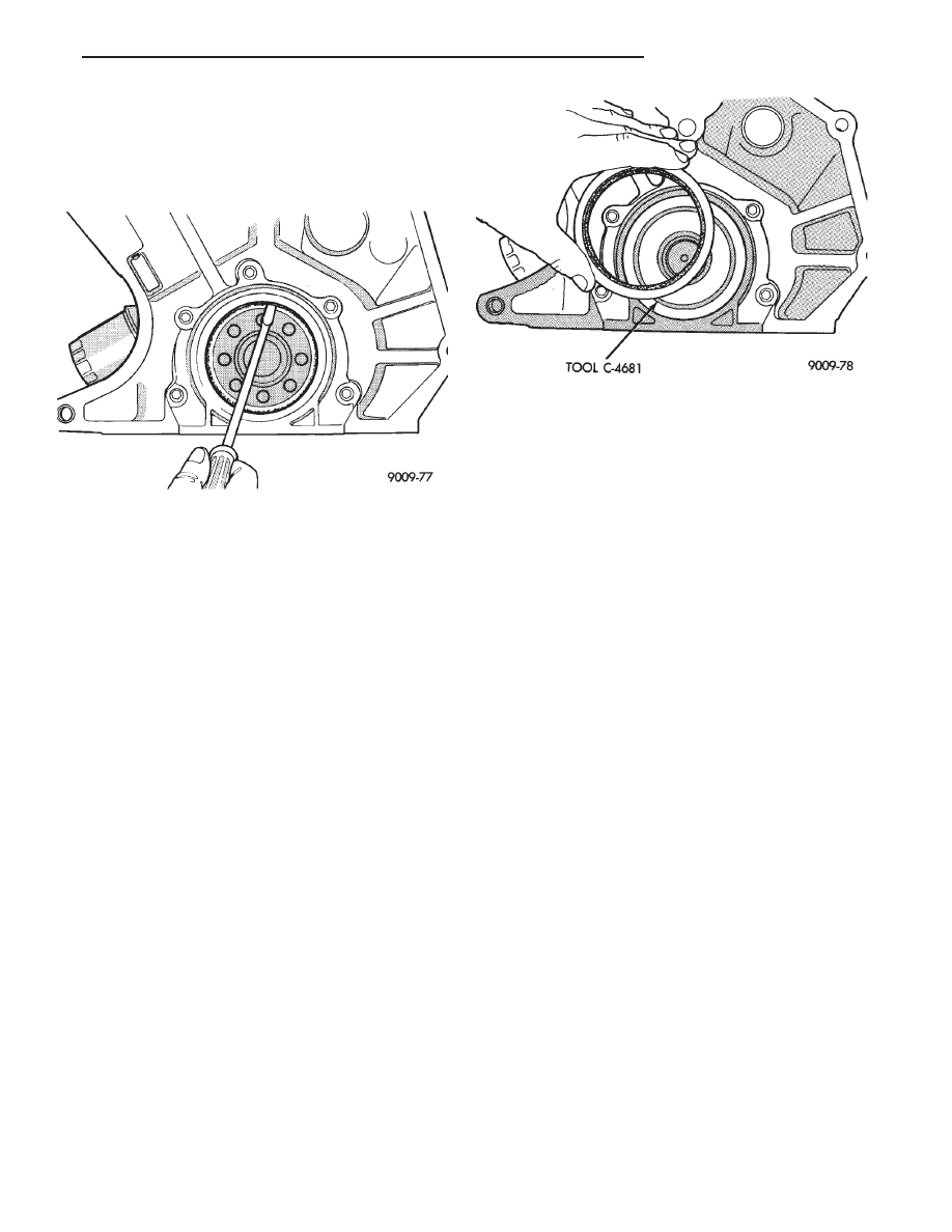
REMOVAL

Pry out rear seal with screwdriver. Be careful not

to nick or damage crankshaft flange seal surface or
retainer bore (Fig. 8).

INSTALLATION

(1) Place Special Seal Pilot Tool C-4681 on crank-

shaft (Fig. 9).

(2) Lightly coat seal O.D. with Loctite Stud N’

Bearing Mount or equivalent.

(3) Place seal over Special Seal Pilot Tool C-4681

and tap in place with a plastic hammer.

REAR CRANKSHAFT SEAL RETAINER

When retainer removal is required, remove re-

tainer clean engine block and retainer of old gasket.
Make sure surfaces are clean and free of oil. Install
new gasket and tighten screws to 12 N

Im (105 in.

lbs.).

Fig. 9 Installing Rear Crankshaft Oil Seal

Fig. 8 Removing Rear Crankshaft Oil Seal

Ä

3.3/3.8L ENGINE

9 - 121

ENGINE LUBRICATION SYSTEM

The lubrication system is a full flow filtration pres-

sure feed type. Oil from the oil pan is pumped by a
internal gear type oil pump directly coupled to the
crankshaft. Its pressure is regulated by a relief valve
located in the Chain Case Cover. The oil is pumped
through an oil filter and feeds a main oil galley.This
oil gallery feeds oil under pressure to the main and
rod bearings, camshaft bearings. Passages in the cyl-
inder block feed oil to the hydraulic lifters and
rocker shaft brackets which feeds the rocker arm piv-
ots (Fig. 1).

OIL PAN SERVICE

REMOVAL

(1) Disconnect negative battery cable, remove en-

gine oil dipstick.

(2) Raise vehicle. Drain engine oil.
(3) Remove oil pan screws and remove oil pan.

CLEANING AND INSPECTION

(1) Clean oil pan in solvent and wipe dry with a

clean cloth. Clean all gasket material from mounting
surfaces of pan and block.

(2) Inspect oil drain plug and plug hole for stripped

or damaged threads and repair as necessary. Install
a new drain plug gasket. Tighten to 27 N

Im (20 ft.

lb.).

(3) Inspect oil pan mounting flange for bends or

distortion. Straighten flange if necessary.

(4) Clean oil screen and pipe in clean solvent. In-

spect condition of screen.

INSTALLATION

(1) Install oil pick-up tube into Chain Case Cover

tighten screw to 28 N

Im (250 in. lbs.) (Fig. 2).

(2) Apply a 1/8 inch bead of Mopar Silicone Rubber

Adhesive Sealant or equivalent, at the parting line of
the chain case cover and the rear seal retainer (Fig. 3).

(3) Use a new pan gasket (Fig. 4).
(4) Install pan and tighten screws to 23 N

Im (200 in.

lb.).

(5) Lower vehicle and install oil dipstick.
(6) Connect negative battery cable.
(7) Fill crankcase with oil to proper level.

Fig. 1 Engine Oiling System

Fig. 2 Oil Pump Pick-up Tube Service

9 - 122

3.3/3.8L ENGINE

Ä

OIL PUMP SERVICE

It is necessary to remove the oil pan, oil pickup

and chain case cover (CCC) to service the oil pump
rotors. The oil pump pressure relief valve can be ser-
viced by removing the oil pan and oil pickup tube.
Refer to Timing Chain Cover Removal and Installa-
tion of this section for procedures.

DISASSEMBLY

(1) To remove the relief valve, proceed as follows:

(a) Drill a 3.175mm (1/8 inch) hole into the relief

valve retainer cap and insert a self-threading sheet
metal screw into cap.

(b) Clamp screw into a vise and while supporting

chain case cover (CCC), remove cap by tapping
CCC using a soft hammer. Discard retainer cap
and remove spring and relief valve (Fig. 5).

(2) Remove oil pump cover screws, and lift off

cover.

(3) Remove pump rotors.
(4) Wash all parts in a suitable solvent and inspect

carefully for damage or wear (Fig. 6).

INSPECTION AND REPAIR

(1) Clean all parts thoroughly. Mating surface of

the chain case cover (CCC) should be smooth. Re-
place pump cover if scratched or grooved.

(2) Lay a straightedge across the pump cover sur-

face (Fig. 7). If a .076mm (.003 inch) feeler gauge can
be inserted between cover and straight edge, cover
should be replaced.

(3) Measure thickness and diameter of outer rotor.

If outer rotor thickness measures 7.64mm (0.0301
inch.) or less (Fig. 8), or if the diameter is 79.95mm
(3.148 inches.) or less, replace outer rotor.

(4) If inner rotor measures 7.64mm (.301 inch) or

less replace inner rotor (Fig. 9).

(5) Slide outer rotor into CCC, press to one side

with fingers and measure clearance between rotor
and CCC (Fig. 10). If measurement is .39mm (.015
inch) or more, replace CCC only if outer rotor is in
specification.

(6) Install inner rotor into CCC. If clearance be-

tween inner and outer rotors (Fig. 11) is .203mm
(.008 inch) or more, replace both rotors.

Fig. 3 Oil Pan Sealing

Fig. 4 Oil Pan Gasket Installation

Fig. 5 Oil Pressure Relief Valve

Fig. 6 Oil Pump

Ä

3.3/3.8L ENGINE

9 - 123

(7) Place a straightedge across the face of the CCC,

between bolt holes. If a feeler gauge of .102mm (.004
inch) or more can be inserted between rotors and the
straightedge, replace pump assembly (Fig. 12). ONLY
if rotors are in specs.

(8) Inspect oil pressure relief valve plunger for scor-

ing and free operation in its bore. Small marks may be
removed with 400-grit wet or dry sandpaper.

(9) The relief valve spring has a free length of

approximately 49.5mm (1.95 inches) it should test
between 19.5 and 20.5 pounds when compressed to
34mm (1-11/32 inches). Replace spring that fails to
meet specifications (Fig. 5).

(10) If oil pressure is low and pump is within speci-

fications, inspect for worn engine bearings or other
reasons for oil pressure loss.

OIL PUMP ASSEMBLY AND INSTALLATION

(1) Assemble pump, using new parts as required.

Install the inner rotor with chamfer facing the
cast iron oil pump cover.

(2) Tighten cover screws to 12 N

Im (105 in. lbs.).

(3) Prime oil pump before installation by filling ro-

tor cavity with engine oil.

(4) Install chain case cover slowly refer to Timing

Chain Cover Installation of this section.

Fig. 9 Measuring Inner Rotor Thickness

Fig. 10 Measuring Outer Rotor Clearance in

Housing

Fig. 11 Measuring Clearance Between Rotors

Fig. 7 Checking Oil Pump Cover Flatness

Fig. 8 Measuring Outer Rotor Thickness

9 - 124

3.3/3.8L ENGINE

Ä


Content   ..  594  595  596  597   ..