Chrysler Le Baron, Dodge Dynasty, Plymouth Acclaim. Manual - part 594


  Index      Chrysler     Chrysler Le Baron, Dodge Dynasty, Plymouth Acclaim - service repair manual 1993 year


Search            


Content   ..  592  593  594  595   ..


Chrysler Le Baron, Dodge Dynasty, Plymouth Acclaim. Manual - part 594


(9) Measure camshaft end play. End Play should

measure .0127 to .304 mm (.005 to .012 inches.) .310
mm (.012 inch. Max.). If not within limits install a new
thrust plate.

(10) Each tappet reused must be installed in the

same position from which it was removed. When
camshaft is replaced, all of the tappets must be
replaced
.

CAMSHAFT BEARINGS—ENGINE REMOVED FROM
VEHICLE

REMOVAL

(1) With engine completely disassembled, drive out

rear cam bearing core hole plug.

(2) Install proper size adapters and horseshoe wash-

ers (part of Tool C-3132-A) at back of each bearing shell
to be removed and drive out bearing shells (Fig. 13).

INSTALLATION

(1) Install

new

camshaft

bearings

with

Tool

C-3132-A by sliding the new camshaft bearing shell
over proper adapter.

(2) Position rear bearing in the tool. Install horse-

shoe lock and by reversing removal procedure, care-
fully drive bearing shell into place.

(3) Install remaining bearings in the same manner.

Bearings must be carefully aligned to bring oil holes
into full register with oil passages from the main
bearing. Number two bearing must index with the oil
passage to the left cylinder head and Number three
bearing must index with the oil passage to the right
cylinder head. If the camshaft bearing shell oil holes
are not in exact alignment, remove and reinstall them
correctly. Install a new core hole plug at the rear of
camshaft. Be sure this plug does not leak.

ENGINE CORE OIL AND CAM PLUGS

REMOVAL

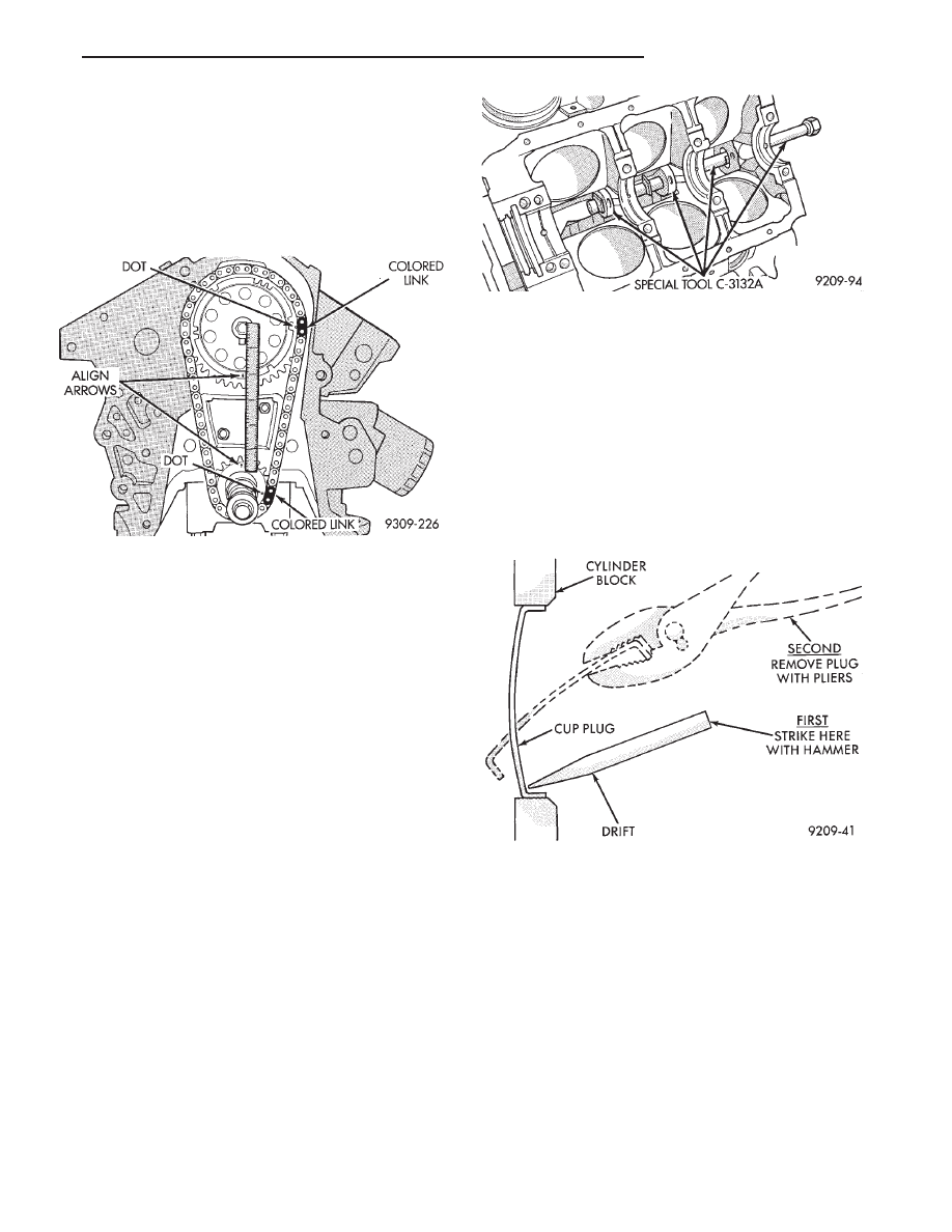
Using a blunt tool such as a drift and a hammer,

strike the bottom edge of the cup plug. With the cup
plug rotated, grasp firmly with pliers or other suit-
able tool and remove plug (Fig. 14).

CAUTION: Do not drive cup plug into the casting as
restricted cooling can result and cause serious en-
gine problems.

INSTALLATION

Thoroughly clean inside of cup plug hole in cylin-

der block or head. Be sure to remove old sealer.
Lightly coat inside of cup plug hole with Loctite Stud
N’ Bearing Mount or equivalent. Make certain the
new plug is cleaned of all oil or grease. Using proper
drive plug, drive plug into hole so that the sharp
edge of the plug is at least 0.5mm (.020 inch) inside
the lead-in chamfer.

It is not necessary to wait for curing of the sealant.

The cooling system can be refilled and the vehicle
placed in service immediately.

Fig. 13 Removed Installation of Camshaft Bearings

with Tool C-3132A—Typical

Fig. 14 Core Hole Plug Removal

Fig. 12 Alignment of Timing Marks

Ä

3.3/3.8L ENGINE

9 - 113

CYLINDER BLOCK, PISTON AND CONNECTING ROD ASSEMBLY SERVICE

CYLINDER BLOCK

PISTON—REMOVAL

(1) Remove top ridge of cylinder bores with a reliable

ridge reamer before removing pistons from cylinder
block. Be sure to keep tops of pistons covered
during this operation. Pistons and connecting
rods must be removed from top of cylinder block.
When removing piston and connecting rod as-
semblies from the engine, rotate crankshaft so
that each connecting rod is centered in cylinder
bore.

(2) Inspect connecting rods and connecting rod caps

for cylinder identification. Identify them if necessary.
(Fig. 2)

(3) Remove connecting rod cap. Install connecting

rod bolt protectors on connecting rod bolts (Fig. 3).
Push each piston and rod assembly out of cylinder
bore.

Be careful not to nick crankshaft journals.
(4) After removal, install bearing cap on the mat-

ing rod.

CLEANING AND INSPECTION

(1) Clean cylinder block thoroughly and check all

core hole plugs for evidence of leaking.

(2) If new core plugs are installed, see Engine Core

Oil and Cam Plugs.

(3) Examine block for cracks or fractures.

Fig. 1 Cylinder Block, Piston and Connecting Rod Assembly

Fig. 2 Identify Connecting Rod to Cylinder

Fig. 3 Connecting Rod Protectors

9 - 114

3.3/3.8L ENGINE

Ä

CYLINDER BORE INSPECTION

The cylinder walls should be checked for out- of-

round and taper with Tool C-119 (Fig. 4). If the cylinder
walls are badly scuffed or scored, the cylinder block
should be replaced.

Measure the cylinder bore at three levels in direc-

tions A and B (Fig. 4). Top measurement should be
12mm (.50 inch) down and bottom measurement
should be 12mm (.50 inch.) up from bottom of bore.
Refer to (Fig. 5) for specifications.

FINISHED PISTONS

All pistons are machined to the same weight in

grams, to maintain piston balance. For cylinder bores
which have been honed, new pistons and connecting
rod assemblies are available for service.

FITTING PISTONS

Piston and cylinder wall must be clean and dry.

Piston diameter should be measured 90 degrees to
piston pin at size location shown in (Fig. 6). Cylinder
bores should be measured halfway down the cylinder
bore and transverse to the engine crankshaft center
line shown in (Fig. 4). Refer to (Fig. 5) for specifica-
tions.

Pistons and cylinder bores should be measured

at normal room temperature, 70°F (21°C)

PISTON PINS

The piston pin rotates in the piston only, and is

retained by the press interference fit of the piston pin
in the connecting rod. The piston pin is not to be
removed damage to the piston may result.

FITTING RINGS

(1) Wipe cylinder bore clean. Insert ring and push

down with piston to ensure it is square in bore. The
ring gap measurement must be made with the ring
positioning at least 12mm (.50 inch) from bottom of
cylinder bore. Check gap with feeler gauge (Fig. 7).

Fig. 5 Cylinder Bore and Piston Specifications

Fig. 6 Piston Measurements

Fig. 7 Check Gap on Piston Rings

Fig. 4 Checking Cylinder Bore Size

Ä

3.3/3.8L ENGINE

9 - 115

Refer to specifications (Fig. 8).

(2) Check piston ring to groove clearance: (Fig. 9).

Refer to specification (Fig. 8).

PISTON RINGS—INSTALLATION

(1) The No. 1 and No. 2 piston rings have a differ-

ent cross section. Install rings with manufacturers
I.D. mark facing up, to the top of the piston (Fig. 10).

CAUTION: Install piston rings in the following or-
der:

(a) Oil ring expander.
(b) Upper oil ring side rail.
(c) Lower oil ring side rail.
(d) No. 2 Intermediate piston ring.
(e) No. 1 Upper piston ring.

(2) Install the side rail by placing one end between

the piston ring groove and the expander. Hold end
firmly and press down the portion to be installed un-
til side rail is in position. Do not use a piston ring
expander. 
(Fig. 11).

(3) Install upper side rail first and then the lower

side rail.

(4) Install No. 2 piston ring and then No. 1 piston

ring (Fig. 12).

Fig. 8 Piston Ring Specifications

Fig. 9 Measuring Piston Ring Side Clearance

Fig. 10 Piston Ring Installation

Fig. 11 Installing Side Rail

Fig. 12 Installing Upper and Intermediate Rings

9 - 116

3.3/3.8L ENGINE

Ä


Content   ..  592  593  594  595   ..