Chrysler Le Baron, Dodge Dynasty, Plymouth Acclaim. Manual - part 592


  Index      Chrysler     Chrysler Le Baron, Dodge Dynasty, Plymouth Acclaim - service repair manual 1993 year


Search            


Content   ..  590  591  592  593   ..


Chrysler Le Baron, Dodge Dynasty, Plymouth Acclaim. Manual - part 592


(3) Before removing valves,remove any burrs

from valve stem lock grooves to prevent damage
to the valve guides. 
Identify valves to insure instal-
lation in original location.

VALVE INSPECTION

(1) Clean valves thoroughly and discard burned,

warped and cracked valves.

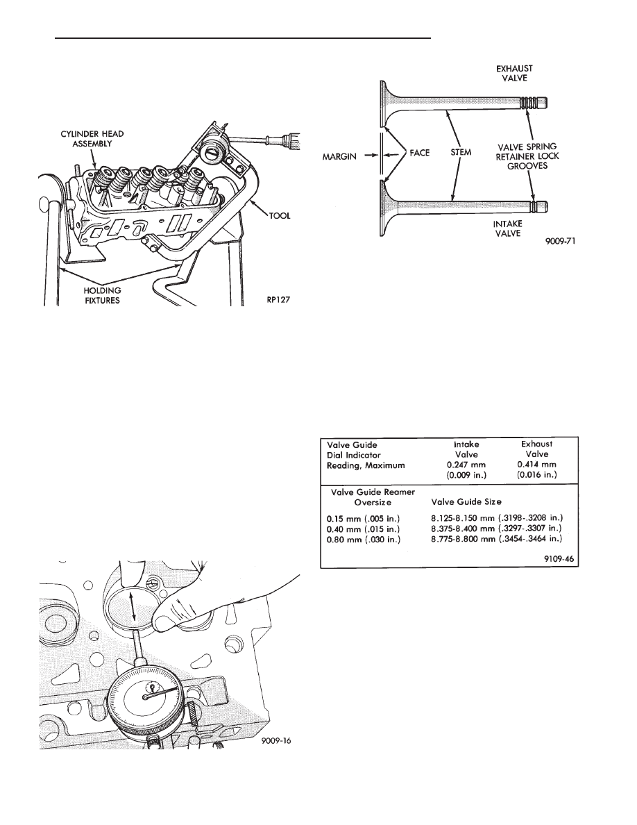
(2) Measure valve stems for wear. Refer to specifica-

tions (Fig. 19).

Valve stems are chrome plated and should not

be polished.

(3) Remove carbon and varnish deposits from inside

of valve guides with a reliable guide cleaner.

(4) Measure valve stem guide clearance as follows:

(a) Install valve into cylinder head so it is 14mm

(.551 inch) off the valve seat. A small piece of hose
may be used to hold valve in place.

(b) Attach dial indicator Tool C-3339 to cylinder

head and set it at right angle of valve stem being
measured (Fig. 17).

(c) Move valve to and from the indicator. Refer to

specifications (Fig. 19).
Ream the guides for valves with oversized stems if

dial indicator reading is excessive or if the stems are
scuffed or scored.

(5) Service valves with oversize stems and over size

seals are available in 0.15mm (.005 inch), 0.40mm,
(.015 inch) and 0.80mm (.030 inch) oversize.

Oversize seals must be used with oversize

valves.

Reamers to accommodate the oversize valve stem are

as follows:

(6) Slowly turn reamer by hand and clean guide

thoroughly before installing new valve. Do not at-
tempt to ream the valve guides from standard
directly to 0.80mm (.030 inch) Use step procedure
of 0.15mm (.005 inch), 0.40mm (.015 inch) and
0.80mm (.030 inch) so the valve guides may be
reamed true in relation to the valve seat. After
reaming guides, the seat runout should be mea-
sured and resurfaced if necessary. See Refacing
Valves and Valve Seats.

VALVE GUIDES

Replace cylinder head if guide does not clean

up with 0.80mm (.030 inch) oversize reamer, or if
guide is loose in cylinder head.

Fig. 18 Intake and Exhaust Valves

Fig. 19 Valve Guide Specifications

Fig. 16 Compress Valve Springs with Special Tool

C-3422B with adapter 6412

Fig. 17 Measuring Valve Guide Wear

Ä

3.3/3.8L ENGINE

9 - 105

REFACING VALVES AND VALVE SEATS

The intake and exhaust valves have a 44-1/2 to 45

degree face angle. The valve seats have a 45 to 45-
1/2 degree face angle. The valve face and valve seat
angles are shown in (Fig. 21).

VALVES

(1) Inspect the remaining margin after the valves

are refaced Refer to specifications (Fig. 20).

VALVE SEATS

CAUTION: Do not un-shroud cylinder head from
around the valve during valve seat refacing (Fig.
22).

(1) When refacing valve seats, it is important that

the correct size valve guide pilot be used for reseat-
ing stones. A true and complete surface must be ob-
tained.

(2) Measure the concentricity of valve seat using

dial

indicator.

Total

runout

should

not

exceed

.051mm (.002 inch) total indicator reading.

(3) Inspect the valve seat with Prussian blue to de-

termine where the valve contacts the seat. To do

this, coat valve seat LIGHTLY with Prussian blue
then set valve in place. Rotate the valve with light
pressure. If the blue is transferred to the center of
valve face, contact is satisfactory. If the blue is trans-
ferred to top edge of valve face,lower valve seat with a
15 degree stone. If the blue is transferred to the bottom
edge of valve face raise valve seat with a 65 degrees
stone.

Valve seats which are worn or burned can be

reworked, provided that correct angle and seat
width are maintained. Otherwise cylinder head
must be replaced.

(4) When seat is properly positioned the width of

intake seats should be 1.75 to 2.25mm (0.69 to .088
inch) The width of the exhaust seats should be 1.50 to
2.00mm (.059 to .078 inch) (Fig. 21)

(5) Check the valve spring installed height after

refacing the valve and seat (Fig. 24).

TESTING VALVE SPRINGS

Whenever valves have been removed for inspection,

reconditioning or replacement, valve springs should be
tested (Fig. 23). As an example; the compression

Fig. 23 Testing Valve Spring with Tool C-647

Fig. 20 Valve Dimensions

Fig. 21 Valve Seats

Fig. 22 Refacing Valve Seats

9 - 106

3.3/3.8L ENGINE

Ä

length of the spring to be tested is 33.34mm (1-5/16
inches). Turn table of Tool C-647 until surface is in line
with the 33.34mm (1-5/16 inch) mark on the threaded
stud and the zero mark on the front. Place spring over
stud on the table and lift compressing lever to set tone
device. Pull on torque wrench until ping is heard. Take
reading on torque wrench at this instant. Multiply this
reading by two. This will give the spring load at test
length. Fractional measurements are indicated on the
table for finer adjustments. Refer to specifications to
obtain specified height and allowable tensions. Discard
the springs that do not meet specifications.

VALVE INSTALLATION

(1) Coat valve stems with clean engine oil and insert

them in cylinder head.

(2) Check valve tip to spring seat dimension A after

grinding the valve seats or faces. Grind valve tip to give
49.541 to 51.271 mm (1.950 to 2.018 inch.) over spring
seat when installed in the head (Fig. 17). Check valve
tip for scoring, if necessary, the tip chamfer should be
reground to prevent seal damage when the valve is
installed.

(3) Install new cup seals on all valve stems and over

valve guides (Fig. 24). Install valve springs and valve
retainers.

(4) Compress valve springs with Valve Spring Com-

pressor Tool C-3422-B, with adapter 6412 install locks
and release tool. If valves and/or seats are re-
ground, measure the installed height of springs
dimension B, make sure measurements is taken
from top of spring seat to the bottom surface of
spring retainer. If height is greater than 1-19/32
inches, (40.6mm), install a 1/32 inch (.794mm)
spacer in head counterbore to bring spring
height back to normal 1-17/32 to 1-19/32 inch (39.1
to 40.6mm)
.

REPLACE VALVE STEM SEALS OR VALVE
SPRINGS, CYLINDER HEAD NOT REMOVED

(1) Perform fuel system pressure release procedure

before attempting any repairs

(2) Disconnect negative battery cable.

(3) Remove Air Cleaner Cover and hose assembly.
(4) Remove

Intake

Manifold;

Refer

to

Intake/Exhaust Manifold 3.3/3.8L Engine Group 11
Exhaust System and Intake Manifolds of this manual
for removal procedure.

(5) Remove cylinder head covers and spark plugs.
(6) Remove connector wire from ignition coils.
(7) Using suitable socket and flex handle at crank-

shaft pulley retaining screw, turn engine so the num-
ber 1 piston is at Top Dead Center on the compression
stroke.

(8) Remove rocker arms with rocker shaft and in-

stall a dummy shaft. The rocker arms should not be
disturbed and left on shaft.

(9) With air hose attached to spark plug adapter

installed in number 1 spark plug hole, apply 90 to 100
psi air pressure (620.5 to 689 kPa). This is to hold
valves into place while servicing components.

(10) Using Tool C-4682 or Equivalent compress

valve spring and remove retainer valve locks and valve
spring.

(11) The intake valve stem seals should be pushed

firmly and squarely over the valve guide using the
valve stem as guide. Do Not Force seal against top of
guide. When installing the valve retainer locks, com-
press the spring only enough to install the locks.

CAUTION:Do not pinch seal between retainer and top
of valve guide
.

(12) Follow the same procedure on the remaining 5

cylinders using the firing sequence 1-2-3-4-5-6. Make
sure piston in cylinder is at TDC on the valve
spring that is being covered.

(13) Remove spark plug adapter tool .
(14) Remove dummy shaft and install rocker shaft

assembly and tighten screws to 28 N

Im (250 in. lbs.).

Fig. 24 Checking Valve Installed Height

Fig. 25 Installing Valve, Cup Seal, Spring and Re-

tainer

Ä

3.3/3.8L ENGINE

9 - 107

(15) Install rocker arm covers tighten screws to 14

N

Im (120 in. lbs.) and connector to ignition coils.

(16) Install Intake Manifold; Refer to Intake Mani-

fold Installation 3.3/3.8L Engine, Group 11 Exhaust
System and Intake Manifold.

HYDRAULIC TAPPETS

The valve train includes roller tappet assemblies,

aligning yokes and yoke retainer.

Roller tappet alignment is maintained by machined

flats on tappet body being fitted in pairs into six
aligning yokes. The yokes are secured by an alignment
yoke retainer (Fig. 26).

PRELIMINARY STEP TO CHECKING THE HY-
DRAULIC TAPPETS

Before disassembling any part of the engine to cor-

rect tappet noise, read the oil pressure at the gauge.
Install a reliable gauge at pressure sending unit if
vehicle has no oil pressure gauge and check the oil level
in the oil pan. The pressure should be between 30 and
80 psi (206.8 to 551.6 kPa) at 2000 rpm.

The oil level in the pan should never be above the

MAX mark on dipstick, or below the MIN mark. Either
of these two conditions could be responsible for noisy
tappets. Oil Level Check: stop engine after reach-
ing normal operating temperature
. Allow 5 min-
utes to stabilize oil level, check dipstick.

OIL LEVEL TOO HIGH

If oil level is above the MAX mark on dip stick, it is

possible for the connecting rods to dip into the oil while
engine is running and create foam. Foam in oil pan
would be fed to the hydraulic tappets by the oil pump
causing them to become soft and allow valves to seat
noisily.

OIL LEVEL TOO LOW

Low oil level may allow pump to take in air which

when fed to the tappets, causes them to become soft
and allows valves to seat noisily. Any leaks on intake
side of pump through which air can be drawn will
create the same tappet action. Check the lubri-

cation system from the intake strainer to the pump
cover, including the relief valve retainer cap. When
tappet noise is due to aeration, it may be intermittent
or constant, and usually more than one tappet will be
noisy. When oil level and leaks have been corrected,
engine should be operated at fast idle to allow all of the
air inside of the tappets to be bled out.

VALVE TRAIN NOISE DIAGNOSIS

To determine source of valve train noise, operate

engine at idle with cylinder head covers removed and
listen for source of the noise.

Worn valve guides or cocked springs are some-

times mistaken for noisy tappets. If such is the
case, noise may be dampened by applying side
thrust on the valve spring. If noise is not appre-
ciably reduced, it can be assumed the noise is in
the tappet. Inspect the rocker arm push rod
sockets and push rod ends for wear.

Valve tappet noise ranges from light noise to a heavy

click. A light noise is usually caused by excessive
leakdown around the unit plunger which will necessi-
tate replacing the tappet, or by the plunger partially
sticking in the tappet body cylinder. A heavy click is
caused either by a tappet check valve not seating, or by
foreign

particles

becoming

wedged

between

the

plunger and the tappet body causing the plunger to
stick in the down position. This heavy click will be
accompanied by excessive clearance between the valve
stem and rocker arm as valve closes. In either case,
tappet assembly should be removed for inspection and
cleaning.

TAPPET REMOVAL

(1) Refer to Cylinder Head Removal of this section to

remove intake manifold and cylinder heads for access
to tappets for service.

(2) Remove yoke retainer and aligning yokes.
(3) Use Tool C-4129 to remove tappets from their

bores. If all tappets are to be removed, identify tappets
to insure installation in original location.

If the tappet or bore in cylinder block is scored,

scuffed, or shows signs of sticking, ream the bore
to next oversize and replace with oversize tap-
pet.

CAUTION: The plunger and tappet bodies are not
interchangeable. The plunger and valve must always
be fitted to the original body. It is advisable to work on
one tappet at a time to avoid mixing of parts. Mixed
parts are not compatible. Do not disassemble a tap-
pet on a dirty work bench.

DISASSEMBLY (FIG. 27)

(1) Pry out plunger retainer spring clip.

Fig. 26 Roller Tappets Aligning Yoke and Retainer

9 - 108

3.3/3.8L ENGINE

Ä


Content   ..  590  591  592  593   ..