Chrysler Le Baron, Dodge Dynasty, Plymouth Acclaim. Manual - part 579


  Index      Chrysler     Chrysler Le Baron, Dodge Dynasty, Plymouth Acclaim - service repair manual 1993 year


Search            


Content   ..  577  578  579  580   ..


Chrysler Le Baron, Dodge Dynasty, Plymouth Acclaim. Manual - part 579


FITTING RINGS

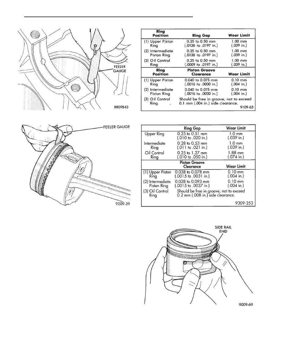
(1) Wipe cylinder bore clean. Insert ring and push

down with piston to ensure it is square in bore. The
ring gap measurement must be made with the ring
positioning at least 12mm (.50 inch) from bottom of
cylinder bore. Check gap with feeler gauge (Fig. 14).
Refer to specifications (Fig. 16 and 17).

(2) Check piston ring to groove clearance: (Fig. 15).

Refer to specification (Figs. 16 and 17).

PISTON RINGS—INSTALLATION

(1) The No. 1 and No. 2 piston rings have a differ-

ent cross section. Install rings with manufacturers
I.D. mark facing up, to the top of the piston (Fig. 13).

CAUTION: Install piston rings in the following or-
der:

(a) Oil ring expander.
(b) Upper oil ring side rail.
(c) Lower oil ring side rail.
(d) No. 2 Intermediate piston ring.
(e) No. 1 Upper piston ring.

(2) Install the side rail by placing one end between

the piston ring groove and the expander. Hold end

Fig. 16 Piston Ring Specifications—Turbo III

Fig. 17 Piston Ring Specifications— Naturally

Aspirated and Flexible Fuel Vehicles

Fig. 18 Installing Side Rail

Fig. 14 Piston Ring Gap

Fig. 15 Piston Ring Groove Clearance

Ä

2.2/2.5L ENGINE

9 - 53

firmly and press down the portion to be installed un-
til side rail is in position. Do not use a piston ring
expander. 
(Fig. 19).

(3) Install upper side rail first and then the lower

side rail.

(4) Install No. 2 piston ring and then No. 1 piston

ring (Fig. 8).

(5) Position piston ring end gaps as shown in (Fig.

19).

(6) Position oil ring expander gap at least 45° from

the side rail gaps but not on the piston pin center or
on the thrust direction. Staggering ring gap is impor-
tant for oil control.

PISTON AND CONNECTING ROD ASSEMBLY
INSTALLATION

(1) Before installing pistons and connecting rod as-

semblies into the bore, besure that compression ring
gaps are staggered so that neither is in line with oil
ring rail gap.

(2) Before installing the ring compressor, make

sure the oil ring expander ends are butted and the
rail gaps located as shown in (Fig. 19).

(3) Immerse the piston head and rings in clean en-

gine oil, slide the ring compressor, over the piston

and tighten with the special wrench (Fig. 20). Be sure
position of rings does not change during this
operation 
.

(4) The valve cut should be toward the manifold side

of the engine (Fig. 21).

(5) Install connecting rod bolt protectors on rod bolts

(Fig. 4).

(6) Rotate crankshaft so that the connecting rod

journal is on the center of the cylinder bore. Insert rod
and piston into cylinder bore and guide rod over the
crankshaft journal.

(7) Tap the piston down in cylinder bore, using a

hammer handle. At the same time, guide connecting
rod into position on connecting rod journal.

(8) Install rod caps. Install nuts on cleaned and oiled

rod bolts and tighten nuts to 54 N

Im (40 ft. lb.) Plus 1/4

turn for N/A engines and 68 N

Im (50 ft. lbs.) for turbo

III engines.

Fig. 19 Piston Ring End Gap Position

Fig. 20 Installing Piston

Fig. 21 Piston Markings

Fig. 22 Checking Connecting Rod Bearing Clear-

ance

9 - 54

2.2/2.5L ENGINE

Ä

CONNECTING RODS

(1) Follow procedure specified in the Standard Ser-

vice Procedures Section for Measuring Main Bearing
Clearance and Connecting Rod Bearing Clearance
(Fig. 22). Refer to specifications (Fig. 25).

CAUTION: Do not rotate crankshaft or the Plastic-
Gage may be smeared.

The rod bearing bolts should be examined be-

fore reuse. If the threads are necked down the
bolts should be replaced (Fig. 23).

Necking can be checked by holding a scale or straight

edge against the threads. If all the threads do not
contact the scale the bolt should be replaced.

(2) Before installing the nuts the threads should be

oiled with engine oil.

(3) Install nuts on each bolt finger tight than alter-

nately torque each nut to assemble the cap properly.

(4) Tighten the nuts to 54 N

Im PLUS 1/4 turn (40 ft.

lbs. PLUS 1/4 turn) for N/A engines Do not use a
torque wrench for last step. 
and 68 N

Im (50 ft. lbs.)

for Turbo III engines.

(5) Using a feeler gauge, check connecting rod side

clearance (Fig. 24). Refer to connecting rod specifica-
tions (Fig. 25).

ENGINE CORE PLUGS

REMOVAL

Using a blunt tool such as a drift or a screwdriver

and a hammer, strike the bottom edge of the cup plug
(Fig. 26). With the cup plug rotated, grasp firmly with
pliers or other suitable tool and remove plug (Fig. 26).

CAUTION: Do not drive cup plug into the casting as
restricted cooling can result and cause serious en-
gine problems.

INSTALLATION

Thoroughly clean inside of cup plug hole in cylinder

block or head. Be sure to remove old sealer. Lightly coat
inside of cup plug hole with sealer. Make certain the
new plug is cleaned of all oil or grease. Using proper
drive plug, drive plug into hole

so that the sharp edge of the plug is at least 0.5mm
(.020 inch) inside the lead-in chamfer (Fig. 26).

It is in not necessary to wait for curing of the seal-

ant. The cooling system can be refilled and the vehi-
cle placed in service immediately.

Fig. 24 Checking Connecting Rod Side Clearance

Fig. 25 Connecting Rod Specifications

Fig. 26 Core Hole Plug Removal

Fig. 23 Checking Bolts for Stretching (Necked)

Ä

2.2/2.5L ENGINE

9 - 55

ENGINE LUBRICATION SYSTEM

Fig. 1 Engine Lubrication Components

9 - 56

2.2/2.5L ENGINE

Ä


Content   ..  577  578  579  580   ..