Chrysler Le Baron, Dodge Dynasty, Plymouth Acclaim. Manual - part 580


  Index      Chrysler     Chrysler Le Baron, Dodge Dynasty, Plymouth Acclaim - service repair manual 1993 year


Search            


Content   ..  578  579  580  581   ..


Chrysler Le Baron, Dodge Dynasty, Plymouth Acclaim. Manual - part 580


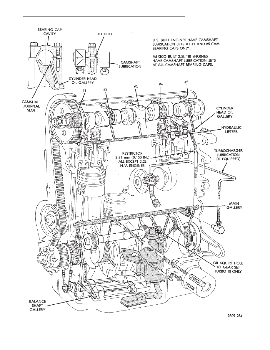
Fig. 2 Engine Lubrication System

Ä

2.2/2.5L ENGINE

9 - 57

OIL PAN

A formed steel oil pan provides lower engine pro-

tection as well as serving as the engine oil reservoir
(Fig. 1). Pan side flanges to block are sealed with
gaskets. The oil pickup tube for some 2.2L engines
have a circular strainer and cover. The 2.5L engine
pickup is also unsupported and the lower end has a
box type strainer (Fig. 4).

PRESSURE LUBRICATION

Oil drawn up through the pickup tube is pressur-

ized by the pump and routed through the full flow
filter to the main oil gallery running the length of
the cylinder block (Fig. 2). Modified oil pickup, pump
and check valve provide increased oil flow to the
main oil gallery.

MAIN/ROD BEARINGS

A diagonal hole in each bulkhead feeds oil to each

main bearing. Drilled passages within the crankshaft
route oil from main bearing journals to crankpin
journals.

ACCESSORY SHAFT

Two separate holes supply the accessory shaft for

the N/A engines. For Turbo III engines there is a slot
in the rear shaft bushing that squirts oil onto the
oil pump drive gears (Fig. 2).

BALANCE SHAFTS

The engine balance shafts are lubricated by an ad-

ditional hole that interconnects a passage in one leg
of the balance shaft carrier to route oil down to the
carrier oil gallery. This gallery directly supplies the
balance shafts front bearings and internal machined
passages in the shafts routes oil from front to rear
shaft bearing journals.

TURBOCHARGER (WHERE EQUIPPED)

If turbocharger equipped, pressurized oil from the

main gallery to sending unit hex fitting is piped from
the fitting to the turbocharger bearing housing.
From the housing a hose and tube connection to a
machined hole in the block provides drainback.

CAMSHAFT/HYDRAULIC LIFTERS

A vertical hole at the number five bulkhead routes

pressurized oil through a restrictor up past a cylinder
head bolt to an oil gallery running the length of the
cylinder head. For 2.2/2.5L and 2.5L FFV engines
hydraulic adjusters are supplied directly from this
gallery while diagonal holes supply oil to the cam-
shaft journals. The camshaft journals are partially
slotted to allow a predetermined amount of pressur-
ized oil to pass into the bearing cap cavities with
small holes directed to spray lubricate the camshaft
lobes. For Turbo III engines oil is supplied thru oil
galleries in the head to the camshafts and rocker

arm shafts which feed oil to the lash adjusters. Oil is
feed thru the rocker arms to lubricate the rollers and
the camshaft lobes.

SPLASH LUBRICATION

Oil returning to the pan from pressurized compo-

nents supplies lubrication to the valve stems. Cylinder
bores and wrist pins are splash lubricated from di-
rected holes in the connecting rods.

OIL PAN

REMOVAL

(1) Drain engine oil and remove oil pan.
(2) Clean oil pan and all gasket surfaces.

OIL PAN RAIL TO BLOCK SEALING

For all engines side gaskets (Fig. 1) are employed for

rail sealing.

INSTALLATION

(1) Apply Mopar Silicone Rubber Adhesive Sealant

or equivalent at the front seal retainer parting line
(Fig. 3).

(2) Install the oil pan side gaskets to the block. Use

heavy grease or Mopar Silicone Rubber Adhesive Seal-
ant or equivalent to hold in place.

(3) Apply Mopar Silicone Rubber Adhesive Sealant

or equivalent to ends of new oil pan end seals at
junction of cylinder block pan rail gasket (Fig. 3).

(4) Install pan and tighten to (12) M8 screws to 23

N

Im (200 in. lbs.) and 1 M6 screws to 12 NIm (105 in.

lbs.).

OIL PUMP SERVICE

OIL PICKUP

(1) Remove screw on pump cover holding oil pick-up

tube to oil pump (Fig. 4).

(2) Remove oil pick-up tube. When reinstalling

make sure to use a new O-Ring on pickup tube.

Fig. 3 Sealing, Front and Rear End Seals

9 - 58

2.2/2.5L ENGINE

Ä

OIL PUMP

REMOVAL

(1) Remove two (2) screws holding oil pump to cyl-

inder block assembly (Fig. 5).

INSTALLATION

(1) Apply Mopar Gasket Maker to pump body-to-

block interface (machined surface).

(2) Lubricate oil pump rotor & shaft and drive

gear.

(3) Turn crankshaft and intermediate shaft until

markings on sprockets are in line (arrows Fig. 6).

(4) Slot in oil pump shaft must be parallel to cen-

ter line of crankshaft when intermediate shaft and
crankshaft are properly timed (Fig. 7).

(5) Install pump full depth and rotate back and

forth slightly to ensure proper positioning and align-
ment through full surface contact of pump and block
machined interface surfaces (Fig. 5).

Fig. 4 Oil Pick-Up

Fig. 5 Oil Pump Assembly

Fig. 6 Crankshaft and Intermediate Shaft Timing

Fig. 7 Oil Pump Shaft Alignment

Ä

2.2/2.5L ENGINE

9 - 59

CAUTION: Pump must be held in fully seated posi-
tion (described above) while installing screws.

(6) Tighten screws to 23 N

Im (200 in. lbs.).

INSPECTION

(1) Check rotor end clearance with feeler gauge as

shown in (Fig. 8).

(2) Limits:

• 0.03mm (.001 inch) minimum.

• 0.09mm (.0035 inch) maximum.

(3) Thickness: 23.96mm (.9435 inch) minimum.

Outer Diameter: 62.7mm (2.469 inch) minimum (Fig.
9).

(4) Install with large chamfered edge in pump

body (Fig. 9).

Clearance: 0.20mm (.008 inch) maximum (Fig. 10).

Clearance: 0.35mm (.014 inch) maximum (Fig. 11).

Clearance: 0.076mm (.003 inch) maximum (Fig.

12).

Oil pressure relief valve spring: Free length:

49.5mm (1.95 inch). Load: 89 N at 34mm. Load: (20
lbs. at 1.34 inch) (Fig. 13).

Thickness: 23.96mm (.9435 inch) Minimum (Fig.

14).

CHECKING ENGINE OIL PRESSURE

(1) Remove pressure sending unit and install Spe-

cial Tool S-94 with gauge assembly C-3292 (Fig. 15).

(2) Warm engine at high idle until thermostat

opens.

CAUTION: If oil pressure is 0 at idle, Do Not Run
engine at 3000 RPM

Fig. 8 Checking Rotor End Clearance

Fig. 9 Measuring Outer Rotor

Fig. 10 Clearance Between Rotors

Fig. 11 Outer Rotor Clearance

9 - 60

2.2/2.5L ENGINE

Ä


Content   ..  578  579  580  581   ..