Chrysler Le Baron, Dodge Dynasty, Plymouth Acclaim. Manual - part 574


  Index      Chrysler     Chrysler Le Baron, Dodge Dynasty, Plymouth Acclaim - service repair manual 1993 year


Search            


Content   ..  572  573  574  575   ..


Chrysler Le Baron, Dodge Dynasty, Plymouth Acclaim. Manual - part 574


CAUTION: Do not use a impact wrench to remove
pulley bolts.

(6) Remove lower timing belt cover fasteners (Fig.

1). Remove cover.

INSTALLATION

(1) Raise vehicle on hoist. Install lower timing belt

cover and tighten fasteners to 12 N

Im (105 in. lbs.)

torque (Fig. 4).

CAUTION: Do not use impact wrench on accessory
drive belt tensioner bolt. It may cause damage to
tensioner arm. Accessory drive belt tensioner pul-
ley bolt must be installed finger tight.

(2) Install accessory drive belt tensioner pulley

bolt finger tight. Then tighten bolt to 54 N

Im (40 ft.

lbs.) torque (Fig. 4).

(3) Install crankshaft and water pump pulleys

(Fig. 3).

(4) Install inner splash shield and wheel (Fig. 2).
(5) Install accessory drive belt. Refer to Cooling

System Group 7 for procedure.

(6) Install upper timing belt cover and tighten

screws to 4 N

Im (36 in. lbs.) torque. Install PCV tube

(Fig. 1).

TIMING BELT

REMOVAL

(1) Remove timing belt cover refer to timing belt

cover service of this section for procedure.

(2) Lift engine with Engine Support Tool C-4852.

Separate right engine mount (Fig. 5).

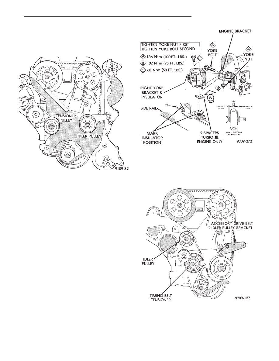
(3) Raise vehicle on a hoist. Remove lower acces-

sory drive belt idler pulley bracket assembly (Fig. 6).

(4) Loosen timing belt tensioner, remove timing

belt and idler pulley (Fig. 6).

(5) Lower vehicle

Fig. 4 Timing Belt Cover and Tensioner

Fig. 5 Right Engine Mount—Typical

Fig. 6 Remove Timing Belt

Ä

2.2/2.5L ENGINE

9 - 33

CAMSHAFT AND CRANKSHAFT TIMING
PROCEDURE

INSTALLATION

(1) Remove air cleaner fresh air duct.
(2) Remove ignition cable cover (Fig. 7).
(3) Remove valve covers and loosen rocker arm as-

semblies about 3 turns as shown in (Fig. 8).

CAUTION: Check lash adjuster for loose or missing
retainers before continuing service procedure.

(4) Align and pin both intake and exhaust cam

sprockets with 3/32 drills or pin punches (Fig. 9). Ac-
cessory Shaft does not need to be timed.

(5) Remove spark plugs.

(6) Install a dial indicator in Number 1 spark plug

hole (Fig. 10).

(7) Rotate crankshaft till number 1 piston is at

Top Dead Center. Mark the engine block for TDC
reference.

(8) Install timing belt and idler pulley in sequence

shown in (Fig. 11).

(9) Remove dial indicator from cylinder head (Fig.

10). Remove drills or pins from camshaft sprockets
(Fig. 11).

(10) Adjust tension to 445 N (110 lbs.) New belt or

311 N (70 lbs.) Used belt . Install belt tension gauge on
timing belt (Fig. 12) adjust tensioner until specified
tension is achieved.

CAUTION: Belt tension gauge must be installed be-
tween the belt teeth to get a accurate reading
.

(11) Rotate crankshaft clockwise 2 full revolutions

and check alignment of camshaft and crankshaft tim-
ing marks. Do not reverse rotate crankshaft or
attempt to rotate engine using cam or accessory
shaft attaching screw.

CAUTION: Do not allow oil or solvents to contact the
timing belt as they can deteriorate the rubber and
cause tooth skipping.

Fig. 7 Ignition Cable Cover

Fig. 8 Rocker Arm Shaft Assemblies

Fig. 9 Camshafts Pinned Into Position

Fig. 10 Dial Indicator Located in Number 1 Cylinder

9 - 34

2.2/2.5L ENGINE

Ä

(12) Recheck belt tension, adjust if necessary.
(13) Torque rocker arm shafts in sequence shown

(Fig. 13) to 12 N

Im (105 in. lbs.) then to 24 NIm (210

in. lbs.).

(14) Install valve covers, spark plugs, ignition cables

and ignition cable cover.

(15) Install air cleaner fresh air duct.
(16) Raise vehicle. Install lower timing belt cover

and accessory drive belt tensioner pulley. Refer to
procedure in this section.

(17) Lower vehicle. Install right engine mount (Fig.

5).

(18) Inspect foam stuffer block condition and posi-

tion (Fig. 14). Stuffer block should be intact and secure
within the engine bracket tunnel.

(19) Install upper timing belt cover and PCV tube.

Refer to procedure in this section.

(20) Install accessory drive belt. Refer to procedure

in this section.

SERVICING OIL SEALS

Refer to servicing oil seals in this group for proce-

dures.

To service the intake cam seal (Turbo III) the

right engine mount must be removed. Refer to
engine mount removal of this Group.

Fig. 13 Rocker Arm Shaft—Installation

Fig. 14 Foam Stuffer Block Location

Fig. 11 Camshafts and Crankshaft Timing Marks

Fig. 12 Belt Tension Gauge Location

Ä

2.2/2.5L ENGINE

9 - 35

CAMSHAFTS SERVICE

Cylinder Head must be removed from vehicle. Re-

fer to cylinder head removal for procedure.

REMOVAL

(1) Mark rocker arms shafts for reinstallation in

the same position (Fig. 1).

(2) Remove rocker arm assembly attaching bolts in

sequence (Fig. 1 ).

(3) Remove thrust plates from rear of camshafts

(Fig. 2).The intake camshaft uses a wider thrust
plate than exhaust camshaft.

CAUTION: Thrust plates are not the same thickness
and cannot be interchanged.

(4) Before camshaft can be removed from cylinder

head the cam seal must be removed first. Becareful
not to damage seal surface of the camshaft.

(5) Using a screwdriver place it against the side of

the cam lobe push the cam out of the head. The cam
seal will be pushed out by the cam (Fig. 3).

(6) Slide the camshaft out of the cylinder head. Be-

careful not scratch the bearing surfaces in the head
(Fig. 4).

CAUTION: Intake and Exhaust camshafts are not in-
terchangeable
.

INSPECTION

Camshaft lobe wear should not exceed .25mm (.010

inch). To measure cam lobe wear (Fig. 4), measure
lobe diameter in two places at the largest diameter
(over the nose). Take first reading with micrometer
in unworn area at the edge of the lobe. Take second
reading in the worn area where rocker arm contacts
the lobe. Subtract second reading from the first. The
difference is the cam lobe wear.

INSTALLATION

(1) Lubricate camshaft journals with clean engine

oil. Carefully install camshaft into the head.

CAUTION: Camshafts are not interchangeable. The
intake cam has a wider thrust plate groove.

Fig. 3 Removing Camshaft Oil Seal

Fig. 1 Rocker Arm Shaft Removal Sequence

Fig. 2 Camshaft Thrust Plates

Fig. 4 Camshaft—Removal or Installation

9 - 36

2.2/2.5L ENGINE

Ä


Content   ..  572  573  574  575   ..