Chrysler Le Baron, Dodge Dynasty, Plymouth Acclaim. Manual - part 573


  Index      Chrysler     Chrysler Le Baron, Dodge Dynasty, Plymouth Acclaim - service repair manual 1993 year


Search            


Content   ..  571  572  573  574   ..


Chrysler Le Baron, Dodge Dynasty, Plymouth Acclaim. Manual - part 573


(2) Inspect each valve spring for squareness with a

steel square and surface plate, test springs from both
ends. If the spring is more than 1.5mm (1/16 inch)
out of square, install a new spring.

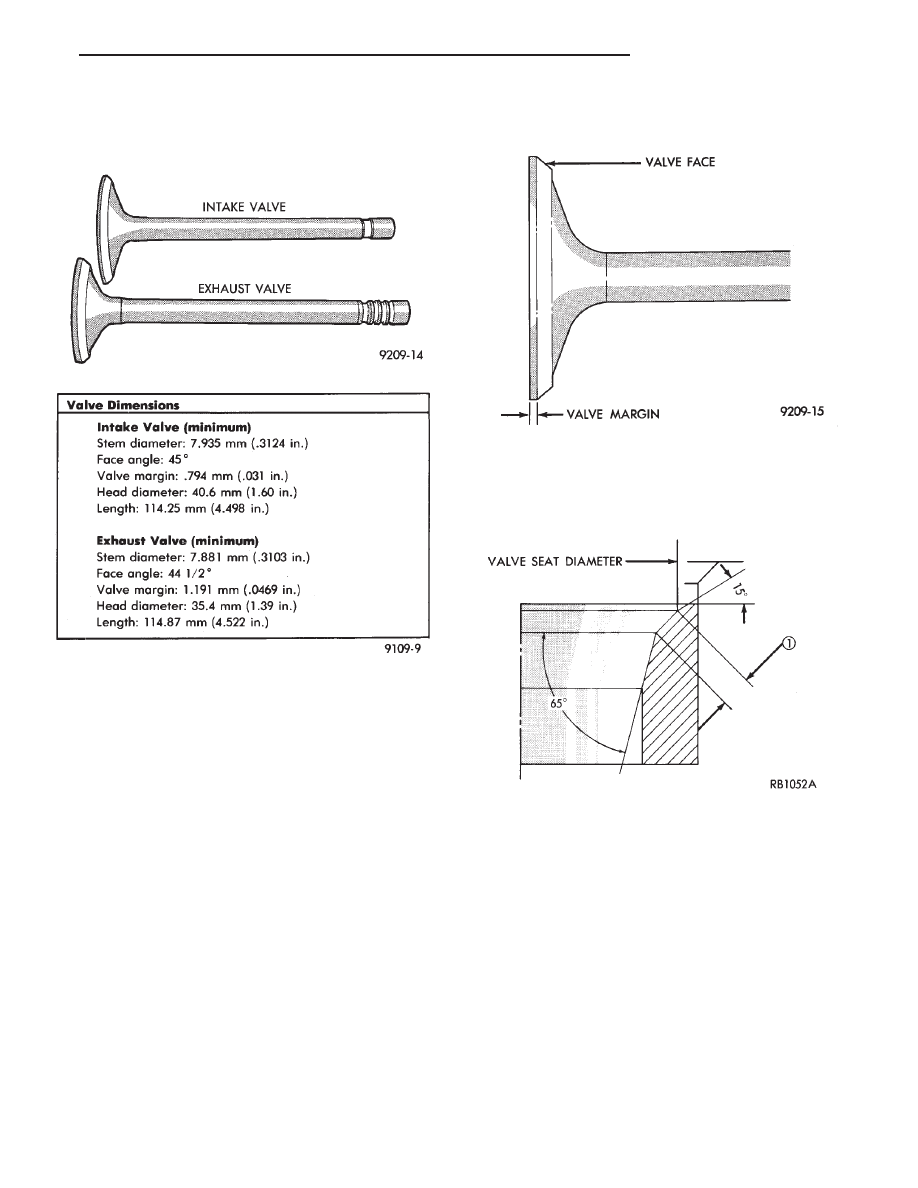
REFACING VALVES AND VALVE SEATS

(1) The intake and exhaust valve seats and valve

face have a 45 degree angle.

(2) Inspect the remaining margin after the valves are

refaced (Fig. 23). Exhaust valves with less than
1.191mm (3/64 inch) margin and intake valves with less
than .794mm (1/32 inch) margin should be discarded.

(3) When refacing valve seats, it is important that

the correct size valve guide pilot be used for reseating
stones. A true and complete surface must be obtained.

(4) Measure the concentricity of valve seat using a

valve seat dial indicator. Total runout should not ex-
ceed. 051mm (.002 inch) (total indicator reading).

(5) Inspect the valve seat with Prussian blue to deter-

mine where the valve contacts the seat. To do this, coat
valve seat LIGHTLY with Prussian blue then set valve
in place. Rotate the valve with light pressure. If the
blue is transferred to the center of valve face, contact is
satisfactory. If the blue is transferred to top edge of the
valve face, lower valve seat with a 15 degrees stone. If
the blue is transferred to the bottom edge of valve face
raise valve seat with a 65 degrees stone.
• Intake valve seat diameter 40.45mm (1.593 inch)

• Exhaust valve seat diameter 34.84mm (1.371 inch)

Valve seats which are worn or burned can be re-

worked, provided that correct angle and seat width are
maintained. Otherwise cylinder head must be replaced.

(6) When seat is properly positioned the width of

intake seats should be 1.75 to 2.25mm (0.69 to .088
inch) The width of the exhaust seats should be 1.50
to 2.00mm (.059 to .078 inch) (Fig. 24 Dimension 1).

(7) Check valve tip to spring seat dimensions after

grinding the valve seats or faces. Grind valve tip to get
49.76 to 51.04mm (1.960 to 2.009 inch) over spring seat
when installed in the head (Fig. 25). The valve tip di-
ameter should be no less than 7.0mm (0.275 inch), if
necessary, the tip chamfer should be reground to pre-
vent seal damage when the valve is installed.

Fig. 21 Intake and Exhaust Valves

Fig. 22 Valve Dimensions

Fig. 23 Refacing Intake and Exhaust Valves

Fig. 24 Refacing Valve Seats

Ä

2.2/2.5L ENGINE

9 - 29

(8) Check the valve spring installed height after

refacing the valve and seat (Fig. 26).

CAUTION: If more than .5mm (.020 inch) must be
ground from the valve tip, check the clearance be-
tween the rocker arm and the valve spring retainer
if below 1.25mm (.050 inch), grind the rocker arm
ears according to the procedure described in Refac-
ing Valves and Valve Seats.

CLEANING

Clean all valve guides, valves and valve spring as-

semblies thoroughly with suitable cleaning solution
before reassembling.

VALVE GEAR REASSEMBLY AFTER VALVE SERVICE

(1) Coat valve stems with lubrication oil and insert

in cylinder head.

CAUTION: Flexible Fuel Vehicles use unique valve
stem oil seals they are green in color. Standard
valve stem oil seals are NOT 
to be interchanged with
Flexible Fuel Vehicles engines.

(2) Install new valve stem seals on all valves. The

valve stem seals should be pushed firmly and
squarely over valve guide. The lower edge of the seal
should be resting on the valve guide boss.

CAUTION: When oversize valves are used, the cor-
responding oversize valve seal must also be used.
Excessive guide wear may result if oversize seals
are not used with oversize valves.

(3) Install valve spring seats and springs and re-

tainers. Compress valve springs only enough to in-
stall locks, taking care not to misalign the direction
of compression. Nicked valve stems may result from
misalignment of the valve spring compressor.

CAUTION: When depressing the valve spring retain-
ers with Tool C-3422-B the locks can become dislo-
cated. Check to make sure both locks are in their
correct location after removing tool
.

(4) Check installed height of springs. Measurement

is to be taken from the spring seat to the bottom of
the spring retainer. Correct height is 41.2mm to
42.7mm (1.62 to 1.68 inches). If seats have been re-
ground an additional spring seat may be required to
maintain correct installed spring height.

(5) Install adjusters, rocker arms in order, and

camshaft as previously described, see Camshaft-In-
stall. Check for clearance between the projecting ears
(either side of valve tip) of the rocker arms and the
valve spring retainers. At least 1.25 mm (.050 inch)
clearance must be present, if necessary, the rocker
arm ears may be ground to obtain this clearance
(Fig. 26).

(6) Checking dry lash. Dry lash is the amount of

clearance that exists between the base circle of an in-
stalled cam and the rocker arm roller when the ad-
juster is drained of oil and completely collapsed.
Specified dry lash is 0.62 to 1.52 mm (.024 to .060
inch). To completely collapse adjuster for dry lash
measurement, pry off retainer cap, disassemble,
drain the adjuster of oil, reassemble, and install. Af-
ter performing dry lash check, refill adjuster with oil
(do not reuse retainer cap/s) and allow 10 minutes for
adjuster/s to bleed down before rotating cam.

Fig. 25 Valve Tip to Spring Seat Dimensions

Fig. 26 Checking Spring Installed Height and Spring

Retainer Clearance

9 - 30

2.2/2.5L ENGINE

Ä

CYLINDER HEAD AND VALVE ASSEMBLY
SERVICE—TURBO III

CYLINDER HEAD COVER SEALING

(1) Before installation, clean cylinder head and cover

mating surfaces. Make certain rails are flat.

Caution: Do not allow oil or solvents to contact the
timing belt as they can deteriorate the rubber and
cause tooth skipping.

(2) Install covers and gasket assembly to head and

torque to 12 N

Im (105 in.lbs.).

CYLINDER HEAD

REMOVAL

Refer to Intake and Exhaust Manifold Service in

Exhaust Systems and Intake Manifold Group 11 for
removal procedure for the intake and exhaust mani-
folds.

(1) The Timing Belt and Solid Mount Compressor

Mount Bracket must be removed before the cylinder
head can be removed. Refer to procedure outlined in
this group for service procedures.

(2) Remove cylinder head bolts.
(3) Cylinder head must be flat within 0.1mm (.004

inch) (Fig. 2).

INSTALLATION

CAUTION: The Turbo III head gasket is not the same
as any other engine head gasket 
(Fig. 3).

CAUTION: Head bolt diameter is 11mm. These bolts
are Unique to this engine application they are not
interchangeable with other engines.

The Cylinder head bolts are torqued using a

new procedure they should be examined BE-
FORE reuse. If the threads are necked down the
bolts should be replaced. (Fig. 4 ).

Necking can be checked by holding a scale or

straight edge against the threads. If all the threads
do not contact the scale the bolt should be replaced.

Fig. 2 Checking Cylinder Head Flatness

Fig. 3 Cylinder Head Gaskets

Fig. 4 Checking Bolts for Stretching—Necking

Fig. 1 Cylinder Head Valve Cover and Gasket As-

sembly

Ä

2.2/2.5L ENGINE

9 - 31

Before installing the bolts, the threads should be

cleaned and oiled.

Tighten the cylinder head bolts in the sequence

shown in (Fig. 5 ). Using the 4 step torque turn
method, tighten according to the following values:
• First All to 61 NIm (45 ft. lbs.)

• Second All to 88 NIm (65 ft. lbs.)

• Third All (again) to 88 NIm (65 ft., lbs.)

• Fourth + 1/4 Turn Do not use torque wrench
for this step.
• Bolt torque after 1/4 turn should be over 90 ft. lbs.
If not, replace the bolt.

Refer to Intake and Exhaust Manifold Service in

Exhaust Systems and Intake Manifold Group 11 for
installation procedure.

Refer to the Timing Belt and Solid Mount Com-

pressor Mount Bracket service procedures in this
group for installations procedures.

TIMING BELT COVER SERVICE—TURBO III
ENGINE

REMOVAL

(1) Remove PCV tube and upper timing belt cover

screws (Fig. 1). Remove upper cover.

(2) Remove accessory drive belt. Refer to Cooling

System Group 7 for procedure.

(3) Raise vehicle on a hoist and remove right

wheel and inner splash shield (Fig. 2).

(4) Remove water pump pulley and crankshaft pul-

ley retaining bolts (Fig. 3), remove pulleys.

(5) Remove lower accessory drive belt idler and

tensioner pulley (Fig. 4).

Fig. 1 Timing Belt Cover Screws

Fig. 5 Cylinder Head Tightening Sequence

Fig. 2 Right Inner Splash Shield

Fig. 3 Crankshaft and Water Pump Pulleys

9 - 32

2.2/2.5L ENGINE

Ä


Content   ..  571  572  573  574   ..