Chrysler Le Baron, Dodge Dynasty, Plymouth Acclaim. Manual - part 571


  Index      Chrysler     Chrysler Le Baron, Dodge Dynasty, Plymouth Acclaim - service repair manual 1993 year


Search            


Content   ..  569  570  571  572   ..


Chrysler Le Baron, Dodge Dynasty, Plymouth Acclaim. Manual - part 571


(2) Turn camshaft until arrows on hub are inline

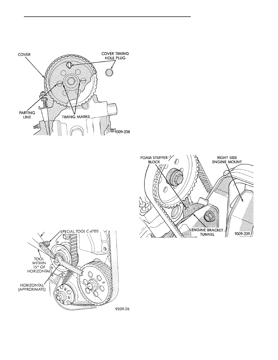
with No. 1 camshaft cap to cylinder headline. Small
hole (arrow Fig. 12) must be in vertical center line.

(3) Install timing belt.

(4) Rotate crankshaft two full revolutions and re-

check timing.

CAUTION: Do not allow oil or solvents to contact
the timing belt as they can deteriorate the rubber
and cause tooth skipping.

(5) Rotate crankshaft till number 1 cylinder is at

the TDC position.

(6) Put belt tension Special Tool C-4703 horizon-

tally on large hex of timing belt tensioner pulley and
loosen tensioner lock nut.

(7) Reset belt tension Special Tool C-4703 index if

necessary to have axis within 15° of horizontal. (Fig.
13)

(8) Turn engine clockwise from TDC two crank revo-

lutions to TDC. Do not reverse rotate crankshaft
or attempt to rotate engine using cam or acces-
sory shaft attaching screw.

(9) Hold weighted wrench in position while tighten-

ing bolt on tensioner to 61 N

Im (45 ft. lbs.) torque.

(10) Lower engine onto engine mount install mount-

ing bolts and tighten to specifications refer to (Fig. 3).

(11) Remove jack from under engine.
(12) Inspect foam stuffer block condition and posi-

tion (Fig. 14). Stuffer block should be intact and secure
within the engine bracket tunnel.

(13) Position both halves of timing belt cover to-

gether (Fig. 4).

(14) Install fasteners holding cover to cylinder head

and block. Tighten fasteners to 4 N

Im (40 in. lbs.)

torque.

(15) Valve Timing Check; (timing belt cover in-

stalled). With number one cylinder at TDC, small hole
in sprocket must be centered in timing belt cover hole
(Fig. 12). If hole is not aligned correctly perform
procedure again.

(16) Install spark plugs.

Fig. 12 Camshaft Timing

Fig. 13 Adjusting Drive Belt Tension

Fig. 14 Foam Stuffer Block Location

Ä

2.2/2.5L ENGINE

9 - 21

CYLINDER HEAD AND VALVE ASSEMBLY SERVICE—EXCEPT TURBO III

Fig. 1 Cylinder Head and Valve Assembly Service

9 - 22

2.2/2.5L ENGINE

Ä

CYLINDER HEAD COVER AND CURTAIN

A curtain aiding air/oil separation is installed on

the cylinder head below the cylinder head cover
(Figs. 1 and 2).

REMOVAL

(1) Remove the cylinder head cover bolts (Fig. 2).
(2) Remove cylinder head cover and curtain from

cylinder head. Do not misplace the rubber bumpers
on curtain.

CLEANING

Before installation, clean cylinder head and cover

mating surfaces. Make certain the rails are flat.

CURTAIN INSTALLATION

Install curtain manifold side first with cutouts over

cam towers and contacting cylinder head floor, then
press opposite distributor side into position below cyl-
inder head rail.

Curtain

is

retained

in

position

with

rubber

bumpers (Fig. 1).

COVER SEALING AND INSTALLATION

Before installation, clean cylinder head and cover

mating surfaces. Make certain rails are flat.

(1) Install new end seals on valve cover.
(2) Apply form-in-place Mopar Silicone Rubber Ad-

hesive Sealant or equivalent gasket material to cyl-
inder head cover rail (Fig. 3). Refer to procedure
detailed in form-in-place gasket section of Standard
Service Procedures, in this Group.

Caution: Do not allow oil or solvents to contact the
timing belt as they can deteriorate the rubber and
cause tooth skipping.

(3) Install curtain, cover and end seal assembly to

head and tighten to 12 N

Im (105 in.lbs.) torque.

CYLINDER HEAD COMPONENTS—IN-VEHICLE
SERVICE

Removal and installation of cylinder head or cam-

shaft require separation of camshaft timing sprocket
from camshaft. To maintain camshaft, intermediate
shaft, and crankshaft timing during service proce-
dures, the timing belt is left indexed on the sprocket
while the assembly is suspended under light tension
(Fig. 4).

When removing the sprocket from the camshaft,

you must maintain adequate tension on the sprocket
and belt assembly to prevent the belt from disengag-
ing with the intermediate or crankshaft timing
sprockets. Refer to Timing System and Seals for re-

Fig. 2 Cylinder Head Cover and Curtain

Fig. 3 Cylinder Head Valve Cover Rail Sealing

Fig. 4 Suspending Camshaft Sprocket

Ä

2.2/2.5L ENGINE

9 - 23

moval and installation of camshaft sprocket proce-
dure and to Camshaft Service for removal and
installation of camshaft procedures.

CAUTION: Failure to maintain adequate tension on
camshaft, intermediate, and crankshaft sprocket
belt can result in lost engine timing. If timing is
lost, refer to Timing System and Seals and (Fig. 4).

CAMSHAFT SERVICE

Refer to TIMING SYSTEM AND SEALS for cam-

shaft timing belt and sprocket removal and installa-
tion, and CYLINDER HEAD In Vehicle Service.

REMOVAL

(1) Remove the cylinder head cover and curtain.
(2) Mark rocker arms for reinstallation in the

same position (Fig. 6).

(3) Loosen camshaft bearing cap screws several

revolutions (Fig. 7).

(4) Jar camshaft at rear of cam to loosen (break

free) the bearing caps. Use a soft faced mallet.

CAUTION: Care should be exercised not to cock the
camshaft during removal. Cocking of the camshaft
could cause damage to the cam or bearing thrust
surfaces.

(5) Remove screws and caps such that cam does

not cock.

INSPECTION

Check bearing cap and oil feed holes for blockage.
Inspect bearing cap and cylinder head journals for

wear and/or oversize, Refer to CYLINDER HEAD,
Inspect and Specifications.

Fig. 5 Engine Sprocket Timing

Fig. 6 Rocker Arm and Lash Adjuster

Fig. 7 Camshaft Cap Removal Sequence

Fig. 8 Camshaft

9 - 24

2.2/2.5L ENGINE

Ä


Content   ..  569  570  571  572   ..