Chrysler Le Baron, Dodge Dynasty, Plymouth Acclaim. Manual - part 569


  Index      Chrysler     Chrysler Le Baron, Dodge Dynasty, Plymouth Acclaim - service repair manual 1993 year


Search            


Content   ..  567  568  569  570   ..


Chrysler Le Baron, Dodge Dynasty, Plymouth Acclaim. Manual - part 569


• Drive shaft distress: See Driveshafts in Suspension,
Group 2.
• Any front end structural damage (after repair).

• Insulator replacement.

ENGINE MOUNT INSULATOR ADJUSTMENT

(1) Remove the load on the engine motor mounts by

carefully supporting the engine and transmission as-
sembly with a floor jack.

(2) Loosen the right engine mount insulator vertical

fasteners, and the front engine mount bracket to front
crossmember screws and nuts.

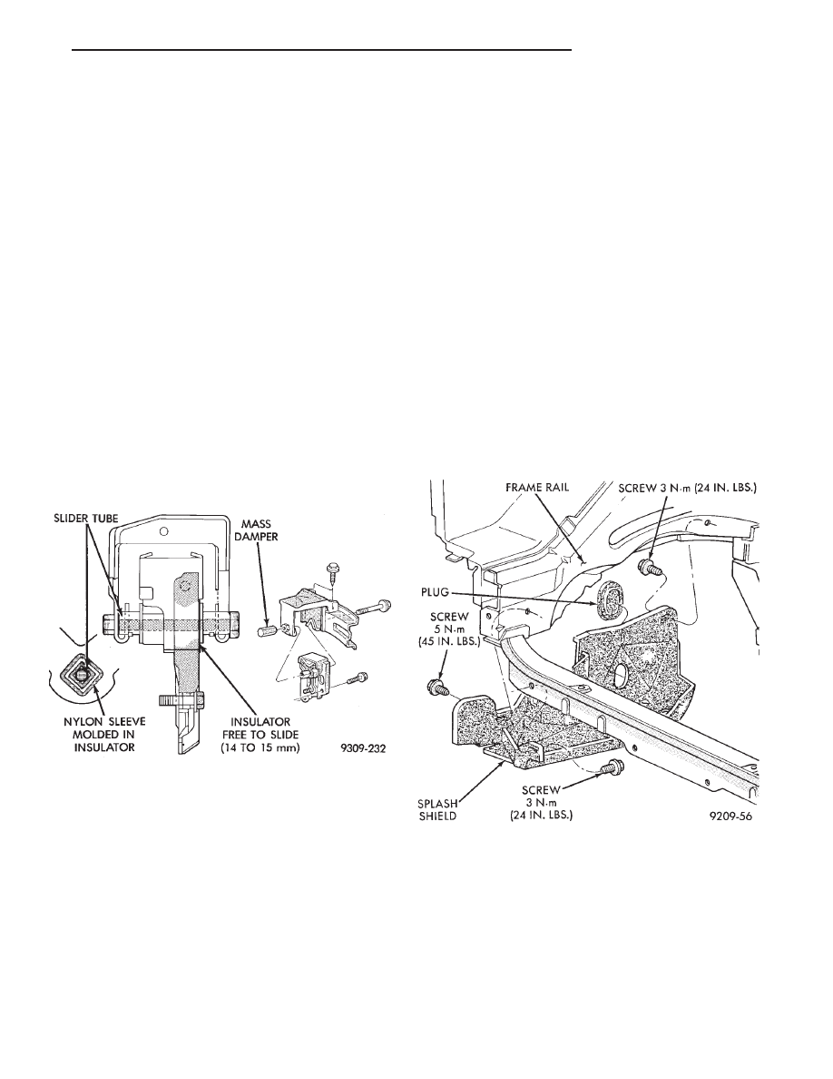
Left engine mount insulator is sleeved over

shaft and long support bolt to provide lateral
movement adjustment with engine weight re-
moved or not.

(3) Pry the engine right or left as required to achieve

the proper drive shaft assembly length. See Drive
Shaft in Suspension Group 2 for driveshaft identifica-
tion and related assembly length measuring.

(4) Tighten right engine mount insulator vertical

bolts to 68 N

Im (50 ft. lbs.). Then tighten front engine

mount screws and nuts to 54 N

Im (40 ft. lbs.) and

center left engine mount insulator.

(5) Recheck drive shaft length.

ENGINE ASSEMBLY

REMOVAL

(1) Disconnect battery.
(2) Scribe hood hinge outline on hood and remove

hood.

(3) Drain cooling system.
(4) Remove hoses from radiator and engine.
(5) Remove radiator and fan assembly.
(6) Remove air cleaner and hoses.
(7) Remove air conditioning compressor mounting

bolts and set compressor aside, if equipped.

(8) Remove power steering pump mounting bolts

and set pump aside

(9) Remove oil filter.
(10) Disconnect fuel line, heater hose and acceler-

ator cable.

(11) Disconnect all electrical connections and har-

nesses at throttle body and engine.

(12) Manual Transmission

(a) Disconnect clutch cable.
(b) Remove transmission case lower cover.
(c) Disconnect exhaust pipe at manifold.
(d) Disconnect starter and lay aside.
(e) Install transmission holding fixture.

(13) Automatic Transmission

(a) Disconnect exhaust pipe at manifold.
(b) Disconnect starter and lay aside.
(c) Remove transmission case lower cover.
(d) Mark flex plate to torque converter.
(e) Remove screws holding torque converter to

flex plate.
(14) Attach C clamp on front bottom of torque con-

verter housing to prevent torque converter from com-
ing out.

(15) Install transmission holding fixture.
(16) Remove right inner splash shield (Fig. 5).

(17) Remove ground strap.
(18) To

lower

engine

separate

right

engine

bracket from yoke bracket To raise engine remove
long bolt through yoke and insulator. IF INSULA-
TOR TO RAIL SCREWS ARE TO BE REMOVED,
MARK INSULATOR POSITION ON SIDE RAIL TO
INSURE EXACT INSTALLATION (Fig. 4).

(19) Remove transmission case to cylinder block

mounting screws.

Fig. 5 Right Inner Splash Shield

Fig. 4 Left Insulator Movement

Ä

2.2/2.5L ENGINE

9 - 13

CAUTION: Make sure clutch cable has been discon-
nected.

(20) Remove front engine mount screw and nut.
(21) Remove manual transmission damper.
(22) Remove left insulator through bolt from inside

wheelhouse or insulator bracket to transmission
screws.

(23) Remove engine from vehicle.

INSTALLATION

(1) Install hoist to the engine and lower engine

into the engine compartment.

SEE: ENGINE MOUNT RUBBER INSULATORS,

THIS GROUP.

(2) Align engine mounts and install but do not

tighten until all mounting bolts have been installed.

(3) Install transmission case to cylinder block

mounting screws. Tighten to 95 N

Im (70 ft. lbs.)

torque.

(4) Remove engine hoist and transmission holding

fixture.

(5) Install ground strap.
(6) Install right inner splash shield.
(7) Connect starter. See Electrical Group 8 for in-

stallation.

(8) Connect exhaust system. See Exhaust Systems

Group 11 for installation.

(9) Manual Transmission: Install transmission

case lower cover.

Automatic Transmission: Remove C clamp from

torque converter housing. Align flexplate to torque
converter and install mounting screws. Tighten to 75
N

Im (55 ft. lbs.) torque.

(10) Manual Transmission: Connect clutch cable.

See Clutch Group 6.

(11) Install power steering pump. Refer to Cooling

System Group 7, Accessory Drive Section for belt
tension adjustment.

(12) Connect fuel line, heater hose, and accelerator

cable.

(13) Connect all electrical connections and har-

nesses at throttle body and engine.

(14) Install oil filter. Fill engine crankcase with

proper oil to correct level.

(15) Install

air

conditioning

compressor

(if

equipped). See Heater and Air Conditioning, Group
24 for installation.

(16) Install air cleaner and hoses.
(17) Install radiator and shroud assembly . Install

radiator hoses. Fill cooling system. See Cooling Sys-
tem Group 7 for filling procedure.

(18) Install hood.
(19) Connect battery.
(20) Start engine and run until operating temper-

ature is reached.

(21) Adjust transmission linkage, if necessary.

SOLID MOUNT COMPRESSOR BRACKET SERVICE

When

service

procedures

require

solid

mount

bracket removal and installation for example: cylin-
der head removal, etc., it is important that bracket
fasteners numbered 1 through 7 (Fig. 4) be removed
and installed in sequence, as instructed in Remove
and Install.

ACCESSORIES REMOVAL

(1) Remove (and install/adjust) belts,see Accessory

Drive Belts in Cooling System,Group 7.

(2) Remove air conditioning compressor (in vehicle

with lines and set aside) (Fig. 6).

(3) Remove generator pivot bolt and remove gener-

ator (in vehicle: turn wiring side up and disconnect,
then rotate generator, pulley end towards engine and
remove).

(4) Remove air conditioner compressor belt idler.

SOLID MOUNT BRACKET—REMOVAL (FIG. 4)

(1) Remove right engine mount yoke screw (see

Engine Remove Fig. 3) securing engine mount sup-
port strut to engine mount bracket.

(2) Remove five side mounting bolts #1, #4 , #5,

#6, and #7 (Fig. 4).

(3) Remove front mounting nut, #2, and remove

front bolt #3*.

(4) Remove front mounting bolt and strut, rotate

solid mount bracket away from engine and slide
bracket on stud until #2 nut mounting stud until
free. Remove spacer from stud.

SOLID MOUNT BRACKET—INSTALLATION

(1) Put spacer onto stud, then install bracket on

front (#2 nut) mounting stud and slide bracket over
timing belt cover into position.

(2) Loosen assembly bracket to engine fasteners

(numbered #1 through #7 in Fig. 6).

(3)

CAUTION: Fasteners MUST BE TIGHTENED IN SE-
QUENCE and to specified torque as follows 
:

• First Bolt #1 to 3.3 NIm (30 in. lbs.)

• Second Nut #2 and Bolt #3 to 54 NIm (40 ft. lbs.).

• Third Bolts #1 (second tightening) #4 and #5 to
54 N

Im (40 ft. lbs.).

• Fourth Bolts #6 and #7 to 54 NIm (40 ft. lbs.).

(4) Install generator and compressor. Tighten com-

pressor mounting bracket bolts to 54 N

Im (40 ft.

lbs.).

SOLID MOUNT COMPRESSOR BRACKET
SERVICE—TURBO III ENGINE

REMOVAL

(1) Disconnect negative battery cable

9 - 14

2.2/2.5L ENGINE

Ä

(2) Remove Accessory Drive Belt. Refer to Cooling

System Group 7 for procedure.

(3) Remove accessory drive belt idler pulley (Fig.

7).

(4) Remove air conditioning compressor and set

aside (Fig. 8).

(5) Remove generator attaching bolts set aside

(Fig. 8).

(6) Remove timing belt covers. Refer to procedure

outlined in this section.

(7) Remove right engine mount yoke bolt. Remove

the fasteners holding the strut into place. Remove
strut from engine (Fig. 9).

(8) Remove

accessory

drive

belt

idler

pulley

bracket (Fig. 9).

(9) Remove timing belt. Refer to procedure out-

lined in this section.

(10) Remove 2 bolts holding solid mount compres-

sor into place, Rotate bracket off engine (Fig. 7).

INSTALLATION

(1) Loosely assemble the bracket to engine with #1

and #2 bolts tighten to 3.3 N

Im (30 in. lbs.) (Fig. 8).

(2) Install timing belt. Refer to procedure outlined

in this section. Install timing belt covers. Refer to
procedure outlined in this section.

(3) Install strut on stud. Tighten nut #3 and bolt

#4, torque to 54 N

Im (40 ft. lbs.) (Fig. 9). Loosen #1

and #2 bolts, then torque to 54 N

Im (40 ft. lbs.) (Fig.

10).Install yoke bolt and torque to 102 N

Im (75 ft.

lbs.).

(4) Install accessory drive belt idler pulley and

bracket (Fig. 8).

(5) Install accessory drive belt tensioner pulley

(Fig. 7).

(6) Install generator (Fig. 8).
(7) Install air conditioning compressor (Fig. 8).
(8) Install accessory drive belt. Refer to Cooling

System Group 7 for procedure.

(9) Connect negative battery cable.

Fig. 6 Solid Mount Compressor Bracket 2.2 & 2.5L Engines

Fig. 7 Accessory Drive System

Ä

2.2/2.5L ENGINE

9 - 15

POWER STEERING/ACCESSORY DRIVE BELT
TENSIONER BRACKET

REMOVAL

(1) Remove Accessory Drive Belt. Refer to Cooling

System Group 7 for procedure.

(2) Remove accessory drive belt tensioner pulley

(Fig. 7).

(3) Remove Timing Belt covers. Refer to procedure

outlined in this section.

(4) Remove Power Steering Pump bolts set pump

aside (Fig. 11).

(5) Loosen timing belt tension. Refer to Camshaft

and Crankshaft Timing Service for procedure. Re-
move timing belt idler pulley bolt (Fig. 12).

CAUTION: Camshaft and Crankshaft Timing may
have to be reset when procedure is completed 
Refer
to procedure outlined in this section.

Fig. 8 Solid Mount Compressor Bracket—Turbo III Engine

Fig. 9 Accessory Drive Idler Pulley Bracket and

Engine Strut

Fig. 10 Compressor Bracket to Cylinder Head

Attaching Bolts

9 - 16

2.2/2.5L ENGINE

Ä


Content   ..  567  568  569  570   ..