Chrysler Le Baron, Dodge Dynasty, Plymouth Acclaim. Manual - part 572


  Index      Chrysler     Chrysler Le Baron, Dodge Dynasty, Plymouth Acclaim - service repair manual 1993 year


Search            


Content   ..  570  571  572  573   ..


Chrysler Le Baron, Dodge Dynasty, Plymouth Acclaim. Manual - part 572


Camshaft bearing journals and lobe wear. Lobe

wear should not exceed .25mm (.010 inch). To mea-
sure cam lobe wear (Fig. 8), measure lobe diameter
in two places at the largest diameter (over the nose).
Take first reading with micrometer in unworn area
at the edge of the lobe. Take second reading in the
worn area where rocker arm contacts the lobe. Sub-
tract second reading from the first. The difference is
the cam lobe wear.

CAMSHAFT END PLAY

(1) Oil camshaft journals and install camshaft

without cam followers. Tighten screws to specified
torque.

(2) Using a suitable tool, move camshaft as far

rearward as it will go.

(3) Zero dial indicator (Fig. 9).
(4) Move camshaft as far forward as it will go.
(5) End play travel: 0.13 - 0.33mm (0.005 - 0.013

inch.).

(6) Remove bearing caps and camshaft.

INSTALLATION

(1) Install cam followers in correct order as re-

moved.

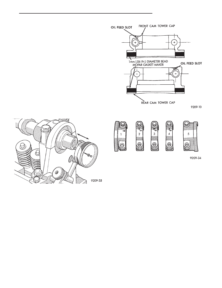
(2) Align camshaft bearing caps in proper sequence

with Cap No. 1 at timing belt end and Cap No. 5 at
transmission end. Arrows on Caps No. 1, 2, 3, 4
must point toward timing belt to prevent cap break-
age (Fig. 11).

(3) Apply Mopar Gasket Maker to No.1 and No.5

bearing cap (Fig. 10).

(4) Caps must be installed before camshaft seals

are installed.

LASH ADJUSTER (TAPPET) NOISE

A tappet-like noise may be produced from several

items. Refer to Lash Adjuster and Tappet Noise - Di-
agnosis in Standard Service Procedures, this Group.

VALVE COMPONENTS REPLACE—CYLINDER
HEAD NOT REMOVED

ROCKER ARM AND HYDRAULIC LASH
ADJUSTER

REMOVAL

(1) Remove valve cover.
(2) For each rocker arm, rotate cam until base cir-

cle is in contact with rocker arm. Depress valve
spring using Special Tool C-4682 (Fig. 12) and slide
rocker arm out. Keep rocker arms in order for reas-
sembly.

(3) Remove hydraulic lash adjuster.

INSTALLATION

(1) Install hydraulic lash adjusters making sure

that adjusters are at least partially full of oil. This is
indicated by little or no plunger travel when the lash
adjuster is depressed.

(2) Rotate cam until base circle is in contact posi-

tion with rocker arm. Depress valve spring with Spe-
cial Tool C-4682 (Fig. 12) and slide rocker arm in
place. Keep rockers in order. It is possible for the

Fig. 9 Camshaft End Play

Fig. 10 Cam Tower Cap Sealing

Fig. 11 Camshaft Bearing Caps Installation

Ä

2.2/2.5L ENGINE

9 - 25

valve spring retainer locks to become dislocated
when depressing the valve spring.Check and make
sure the locks are in their proper location.

(3) Install valve cover as previously outlined in

this section.

VALVE SPRINGS AND VALVE STEM SEALS

REMOVAL

(1) Remove rocker arms as previously outlined in

this section.

(2) Rotate crankshaft until piston is at TDC on

compression.

(3) With air hose attached to adapter tool installed

in spark plug hole, apply 90-120 psi air pressure.

(4) Using Special Tool C-4682 (Fig. 12) compress

valve springs and remove valve locks.

(5) Remove valve spring.
(6) Remove valve stem seal by gently prying side-

to-side with a screwdriver blade. Once dislodged from
guide post, seal may be easily removed.

INSTALLATION

CAUTION: Flexible Fuel Vehicle Valve use unique
valve stem oil seals they are green in color. Stan-
dard valve stem oil seals are NOT 
to be interchanged
with Flexible Fuel Vehicles engines.

(1) Install valve seals (Fig. 13) as outlined in step

(2) of Valve Gear Reassembly - After Valve Ser-
vice 
in this section.

(2) Using Special Tool C-4682 compress valve

springs only enough to install locks. Correct align-
ment of tool is necessary to avoid nicking valve
stems (air pressure required), piston at TDC.

(3) Install rocker arms as previously outlined in

this section.

CYLINDER HEAD

REMOVAL

(1) Perform fuel system pressure release procedure

before attempting any repairs.Refer to Fuel Sys-
tem Group 14

(2) Disconnect negative battery cable. Drain cool-

ing system. Refer to Cooling System, Group 7.

(3) Remove air cleaner and disconnect all vacuum

lines, electrical wiring and fuel lines from throttle
body.

(4) Remove throttle linkage.
(5) Loosen power steering pump and remove belt.
(6) Remove power brake vacuum hose from intake

manifold.

(7) Remove water hoses from water crossover.
(8) Raise vehicle and remove exhaust pipe from

manifold.

(9) Remove power steering pump assembly and set

aside.

(10) Disconnect coil wiring connector and coil wire

from coil.

(11) Disconnect

dipstick

tube

from

thermostat

housing and ROTATE bracket from stud.DO NOT
bend the bracket or tube.

(12) See

Solid

Mount

Compressor

Bracket

in

STANDARD SERVICE PROCEDURES, this Group.

(13) Remove cylinder head bolts.

INSPECT HEAD AND CAMSHAFT BEARING
JOURNALS

(1) Cylinder head must be flat within 0.1mm (.004

inch) (Fig. 14).

(2) Inspect camshaft journals for scoring and jour-

nal caps for oversize markings. When servicing cyl-
inder head or camshaft, it is necessary to be certain
that oversized camshafts are used only in oversized
heads.

Identify oversize components as follows:

Fig. 12 Removing and Installing Valve Spring

Fig. 13 Valve Stem Seals

9 - 26

2.2/2.5L ENGINE

Ä

Cylinder Head: Top of bearing caps painted green

and O/SJ stamped rearward of oil gallery plug on end
of head.

Camshaft: Barrel of camshaft painted green and

O/SJ stamped on end of shaft.

CLEANING

Remove all gasket material from cylinder head and

block. Be careful not gouge or scratch the aluminum
head sealing surface.

INSTALLATION

CAUTION: Head bolt diameter is 11mm. These bolts
are identified with 11 on the head of the bolt. 10mm
bolts will thread into the 11mm hole but will strip the
cylinder block bolt hole
.

Since the Cylinder head bolts are torqued us-

ing a new procedure they should be examined
BEFORE reuse. If the threads are necked down
the bolts should be replaced (Fig. 16)
.

Necking can be checked by holding a scale or straight

edge against the threads. If all the threads do not
contact the scale the bolt should be replaced.

(1) Before installing the bolts the threads should be

oiled with engine oil.

(2) Install both bolts in each cap finger tight, then

alternately torque each bolt to assemble the cap prop-
erly.

(3) Tighten the cylinder head bolts in the sequence

shown in (Fig. 17). Using the 4 step torque turn
method, tighten according to the following values:
• First All to 61 NIm (45 ft. lbs.)

• Second All to 88 NIm (65 ft. lbs.)

• Third All (again) to 88 NIm (65 ft., lbs.)

• Fourth + 1/4 Turn Do not use a torque wrench
for this step.

Bolt torque after 1/4 turn should be over 90 ft. lbs. If

not, replace the bolt.

(4) Rotate dipstick tube or bracket onto stud.

Tighten bracket retaining nut to 23 N

Im (200 in.

lbs.)

VALVE SERVICE—CYLINDER HEAD REMOVED

VALVES AND VALVE SPRINGS

REMOVAL

(1) With cylinder head removed, compress valve

Fig. 15 Cylinder Head Gaskets

Fig. 16 Checking Bolts for Stretching (Necking)

Fig. 17 Cylinder Head Tightening Sequence

Fig. 14 Checking Cylinder Head Flatness

Ä

2.2/2.5L ENGINE

9 - 27

springs using Tool C-3422-B.

(2) Remove valve retaining locks, valve spring re-

tainers, valve stem seals and valve springs.

(3) Before removing valves,remove any burrs

from valve stem lock grooves to prevent damage
to the valve guides. 
Identify valves to insure instal-
lation in original location.

VALVE INSPECTION

(1) Clean valves thoroughly and discard burned,

warped and cracked valves.

(2) Measure valve stems for wear.
(3) If valve stems are worn more than 0.05 mm (.002

inch.) replace valve.

VALVE GUIDES

(1) Remove carbon and varnish deposits from inside

of valve guides with a reliable guide cleaner.

(2) Checking Valve Guide Wear:

• Insert valve with valve head positioned 10 mm (.400
inch) above cylinder head gasket surface.
• Move valve to and from the indicator (Fig. 17). The
total dial indicator reading should not exceed the amount
specified in (Fig. 18). Readings should be taken for length-
wise and crosswise (with respect to cylinder head) move-
ment for each valve. Ream the guides for valves with
oversize stems if dial indicator reading is excessive or if
the stems are scuffed or scored.

(3) Service valves with oversize stems and oversize

seals are available in 0.15mm, (.005 inch) 0.40mm,
(.015 inch) and 0.80mm(.031 inch) oversize.

Oversize seals must be used with oversize

valves.

Reamers sizes to accommodate the oversize valve

stem are shown in (Fig. 18)

(4) Slowly turn reamer by hand and clean guide thor-

oughly before installing new valve. Do not attempt to
ream the valve guides from standard directly to
0.80mm (.030 inch). Use step procedure of 0.15mm
(.005 inch), 0.40mm (.015 inch) and 0.80mm (.030

inch) so the valve guides may be reamed true in
relation to the valve seat. After reaming guides, the
seat runout should be measured and resurfaced if
necessary. Refer to Refacing Valves and Valve Seats.

Replace cylinder head if guide does not clean

up with 0.80 mm (.030 inch) oversize reamer, or if
guide is loose in cylinder head.

TESTING VALVE SPRINGS

(1) Whenever valves have been removed for inspection,

reconditioning or replacement, valve springs should be
tested. As an example, the compression length of the
spring to be tested is 33.34mm (1-5/16 inches). Turn table
of Tool C-647 until surface is in line with the 33.34mm
(1-5/16 inch) mark on the threaded stud and the zero
mark on the front. Place spring over stud on the table and
lift compressing lever to set tone device (Fig. 20). Pull on
torque wrench until ping is heard. Take reading on torque
wrench at this instant. Multiply this reading by two. This
will give the spring load at test length. Fractional mea-
surements are indicated on the table for finer adjust-
ments. Refer to specifications to obtain specified height
and allowable tensions. Discard the springs that do not
meet specifications.

Fig. 18 Checking Wear on Valve Guide—Typical

Fig. 19 Valve Guide Specification

Fig. 20 Testing Valve Spring with Tool C-647

9 - 28

2.2/2.5L ENGINE

Ä


Content   ..  570  571  572  573   ..