Chrysler Le Baron, Dodge Dynasty, Plymouth Acclaim. Manual - part 314


  Index      Chrysler     Chrysler Le Baron, Dodge Dynasty, Plymouth Acclaim - service repair manual 1993 year


Search            


Content   ..  312  313  314  315   ..


Chrysler Le Baron, Dodge Dynasty, Plymouth Acclaim. Manual - part 314


VEHICLE SPEED SENSOR TEST

For testing of the vehicle speed sensor and related

components using DRB II, refer to the appropriate
Powertrain Diagnostics Test Procedure Manual.

PRINTED CIRCUIT BOARD REPLACEMENT

(1) Remove cluster bezel.
(2) Remove instrument cluster.
(3) Remove tachometer drive module, if equipped.
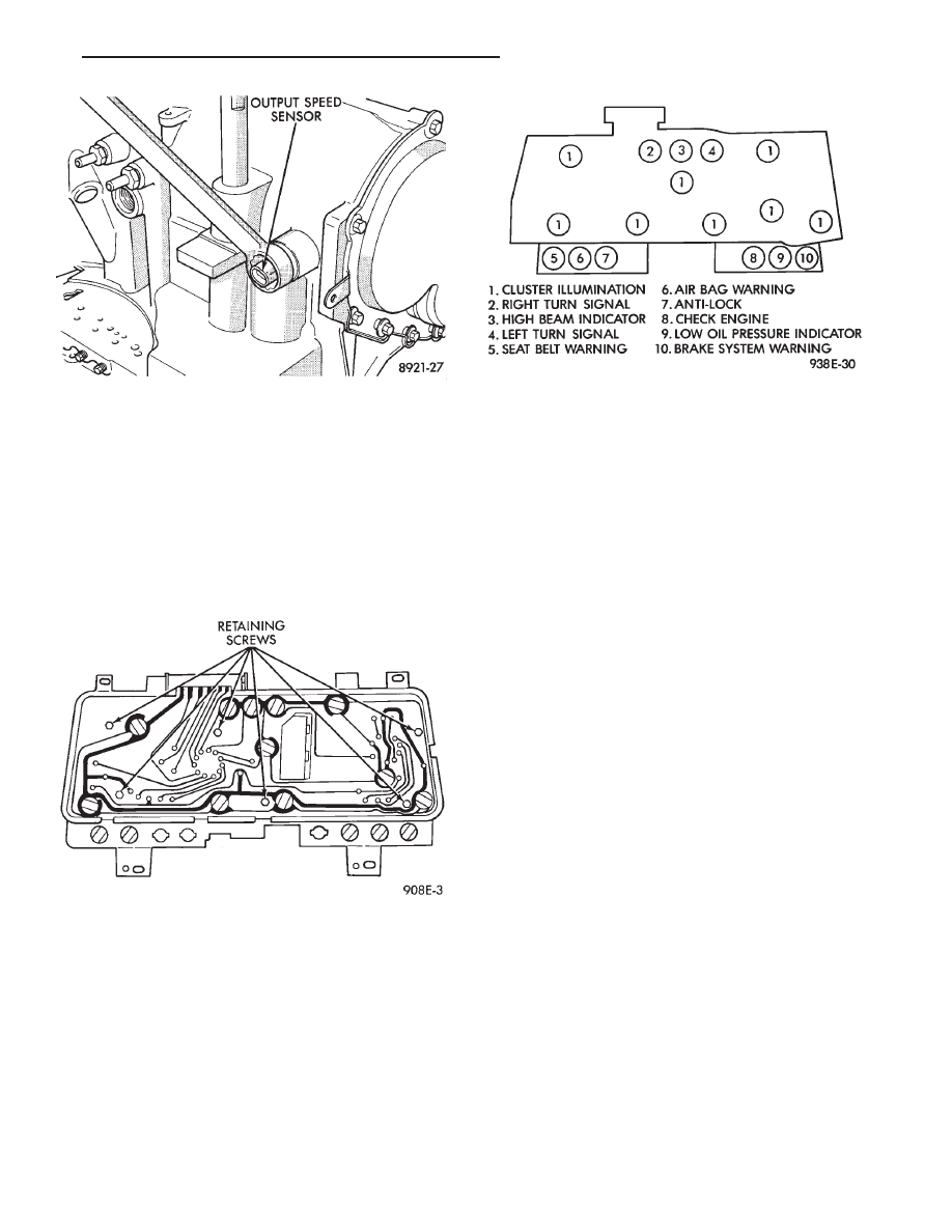
(4) Remove six retaining screws (Fig. 18).

(5) Twist out all illumination and warning lamp

sockets.

(6) Pull printed circuit board from cluster housing.
(7) For installation reverse above procedures. Posi-

tion printed circuit board on cluster housing, being
certain that all gauge pins are inserted correctly.

CLUSTER LAMP REPLACEMENT

Illumination Lamp Chart shows cluster as viewed

from rear. However, all lamps must be replaced by
removing cluster from instrument panel (Fig. 19).

SWITCH AND PANEL COMPONENT SERVICE

LOWER STEERING COLUMN COVER
REPLACEMENT

(1) Disconnect park brake release rod from the

park brake handle.

(2) Remove two screws attaching hood release (Fig.

20).

(3) Remove fuse access door and remove steering

column cover attaching screw located directly above
the fuse block.

(4) Remove six screws around outside of steering

column cover.

(5) Remove steering column cover.
(6) For installation reverse above procedures.

CENTER MODULE LOWER COVER
REPLACEMENT

(1) Open ash receiver and remove center module

bezel.

(2) Remove module cover to instrument panel re-

taining screws (Fig. 20).

(3) Remove module cover from vehicle.
(4) For installation reverse above procedures.

CENTER MODULE BEZEL REPLACEMENT

(1) Open ash receiver.
(2) Grip module bezel around outer edges and pull

rearward to release six spring-type retaining clips
(Fig. 20).

(3) For installation position spring clips to instru-

ment panel and push firmly until seated.

(4) Close ash receiver.

Fig. 17 Vehicle Speed Sensor Removal

Fig. 18 Printed Circuit Board

Fig. 19 Instrument Cluster Illumination Lamps

Ä

INSTRUMENT PANEL AND GAUGES

8E - 67

HEADLAMP SWITCH REPLACEMENT

(1) Snap headlamp switch bezel out of instrument

panel pad (Fig. 21).

(2) Remove three screws securing headlamp switch

mounting plate to instrument panel.

(3) Pull headlamp switch and mounting plate rear-

ward from instrument panel opening.

(4) Disconnect wiring connector from switch.
(5) Remove switch knob by depressing release but-

ton on the bottom on the switch and pulling knob out
from switch.

(6) Snap

headlamp

switch

escutcheon

out

of

mounting plate to gain access to mounting plate re-
taining nut.

(7) Remove headlamp switch to mounting plate re-

taining nut and separate switch from mounting
plate.

(8) For installation reverse above procedures.

A/C HEATER CONTROL REPLACEMENT

(1) Remove center bezel assembly.
(2) Remove A/C control to instrument panel retain-

ing screws (Fig. 22).

(3) Pull control rearward and disconnect tempera-

ture control cable and electrical and vacuum connec-
tors.

(4) Remove control from vehicle.
(5) For installation reverse above procedures.

Fig. 20 Lower Instrument Panel

Fig. 21 Headlamp Switch Assembly

8E - 68

INSTRUMENT PANEL AND GAUGES

Ä

HEATER CONTROL LAMP REPLACEMENT

(1) Remove heater control. Refer to A/C Heater

Control for removal.

(2) Pull control far enough to gain access to the

lamp socket.

(3) Replace lamp. To remove lamp rotate socket

counter clockwise. To install rotate clockwise.

(4) For installation reverse above procedures.

A/C CONTROL LAMP REPLACEMENT

(1) Remove heater control. Refer to A/C Heater

Control for removal.

(2) Pry temperature and blower switch knobs off

with flat blade tool. To protect cosmetic face place
cardboard or similar material on the face plate while
prying.

(3) Remove face plate by lifting on the six tabs.

Three on top and three on bottom of the face plate.

(4) Replace lamp.
(5) For installation reverse above procedures.

HEATER CONTROL BLOWER SWITCH
REPLACEMENT

(1) Remove heater control. Refer to A/C Heater

Control for removal.

(2) Pry temperature and blower switch knobs off

with flat blade tool. To protect cosmetic face place
cardboard or similar material on the face plate while
prying.

(3) Remove face plate by lifting on the six tabs.

Three on top and three on bottom of the face plate.

(4) Pry blower switch off with flat blade tool. To

protect cosmetic face, place cardboard or similar ma-
terial on the face plate while prying.

(5) To replace, line up blower switch terminals and

press firmly until the it bottoms out on the housing.

(6) For installation reverse above procedures.

A/C CONTROL BLOWER SWITCH
REPLACEMENT

(1) Remove heater control. Refer to A/C Heater

Control for removal.

(2) Position the temperature knob at the maximum

heat position to gain screw access.

(3) Remove two screws holding the blower switch

located on top of the control.

(4) Pry the blower switch off with a flat blade tool.
(5) To replace, line up blower switch terminals and

press firmly until the it bottoms out on the housing.

(6) For installation reverse above procedures.

GLOVE BOX MODULE REPLACEMENT

(1) Disconnect battery negative cable and isolate

or remove fuse #13 prior to removing switch or wires
may short to ground.

(2) Open glove box door (Fig. 23).

(3) Remove check strap screws to allow full down-

ward movement of the glove box door.

(4) Remove six screws attaching glove box module

to instrument panel.

(5) Pull glove box module rearward and disconnect

wiring from lamp and switch.

(6) Remove glove box from vehicle.
(7) For

installation

reverse

above

procedures.

When installing glove box module, be sure that left
edge of module is pressed against foam bead on trim
pad. This will assure that there will be an adequate
gap between right edge of glove box door and trim
pad.

ASH RECEIVER ASSEMBLY REPLACEMENT

(1) Open ash receiver and remove center module

bezel.

(2) Remove ash receiver bracket to instrument

panel retaining screws (Fig. 23).

(3) Pull assembly rearward off of locating pins and

disconnect wiring for lamp.

(4) Remove ash receiver from vehicle.
(5) For installation reverse above procedures.

Fig. 22 A/C Heater Control

Fig. 23 Glove Box, Ash Receiver and Cigar Lighter

Ä

INSTRUMENT PANEL AND GAUGES

8E - 69

CIGAR LIGHTER REPLACEMENT

(1) Remove center bezel assembly (Fig. 23).
(2) Remove center module lower cover or open for-

ward console lid.

(3) Unscrew lighter receptacle shell from recepta-

cle and remove from base instrument panel.

(4) Disconnect wiring connectors from lighter re-

ceptacle and remove from vehicle.

(5) For installation reverse above procedures.

REAR WINDOW DEFOGGER AND/OR FOG
LAMP SWITCH REPLACEMENT

(1) Remove center module bezel assembly (Fig. 20).
(2) Remove two switch bezel screws (Fig. 24).

(3) Pull switches and bezel rearward and discon-

nect wiring connector.

(4) Remove two switch retaining screws.
(5) Remove switch from bezel.
(6) For installation reverse above procedures.

INTERMITTENT WIPE MODULE
REPLACEMENT

(1) Remove lower steering column cover.
(2) Slide intermittent wipe module off of bracket

located on steering column reinforcement (Fig. 25).

(3) Disconnect wiring connector from module and

remove module from vehicle.

(4) For installation reverse above procedures.

GLOVE BOX LAMP AND SWITCH
REPLACEMENT

(1) Disconnect battery and/or pull fuse # 13 before

starting removal procedure.

(2) Open glove box door (Fig. 26).
(3) Carefully pry lamp from its mounting surface

with tip of a small screwdriver.

(4) Pull lamp from box and disconnect electrical

leads.

(5) Remove lamp.
(6) For installation reverse above procedures.

CONSOLETTE ASSEMBLY REPLACEMENT

(1) Remove shifter handle.
(2) Unsnap transmission range indicator bezel or

shift boot bezel from consolette, disconnect wiring
and remove bezel assembly (Fig. 27).

(3) Remove two screws from side of armrest.
(4) Remove

four

caps

which

cover

attaching

screws.

(5) Remove four attaching screws.
(6) Lift consolette up and over shift mechanism to

remove.

(7) For installation reverse above procedures.

Fig. 24 Rear Window Defogger and Fog Lamp

Switch

Fig. 25 Intermittent Wipe Module

Fig. 26 Glove Box Lamp and Switch

8E - 70

INSTRUMENT PANEL AND GAUGES

Ä


Content   ..  312  313  314  315   ..