Chrysler Le Baron, Dodge Dynasty, Plymouth Acclaim. Manual - part 315
CENTER CONSOLE ASSEMBLY
REPLACEMENT
(1) Place transmission in neutral and remove
shifter handle.
(2) Unsnap transmission range indication bezel or
shift boot bezel from console, disconnect wiring and
remove bezel assembly (Fig. 27).
(3) Unsnap power window/mirror switch bezel,
when so equipped and disconnect switch wiring.
(4) Remove two screws from side of armrest.
(5) Remove arm rest and center console section as
a unit by lifting from the front and unsnapping from
front console section.
(6) For installation reverse above procedures. Ad-
just transmission range indicator in the PARK posi-
tion.
CONSOLE GEAR SELECTOR INDICATOR LAMP
REPLACEMENT
(1) Place shifter handle in Neutral position.
(2) Remove handle from shifter.
(3) Unsnap gear selector bezel and pull upward
(Fig. 27).
(4) Remove indicator lamp socket from bezel to re-
place lamp.
(5) For installation reverse above procedures. Ad-
just transmission range indicator in the PARK posi-
tion.
FRONT CONSOLE ASSEMBLY REPLACEMENT
(1) Remove shifter handle.
(2) Unsnap transmission range indicator bezel or
shift boot bezel from console assembly, disconnect
wiring and remove bezel assembly (Fig. 27).
(3) Unsnap power mirror/window switch bezel,
when so equipped and disconnect switch wiring.
(4) Open arm rest and remove three screws hold-
ing arm rest to center console retractor bracket.
(5) Remove armrest and center console section as a
unit by lifting and unsnapping from forward console
section.
(6) Remove center module bezel.
(7) Remove forward console and side walls as com-
plete unit by removing six sidewall attaching screws
to instrument panel and console bracket. Slide unit
rearward and lift to remove.
(8) For installation reverse above procedures.
(a) For adjustment move gearshift lever with
force into park position.
(b) Check gear selector indicator for proper
alignment.
INSTRUMENT PANEL TOP COVER
REPLACEMENT
(1) Place trim-stick tool in groove between the
panel top cover and pad surface (FIG. 28).
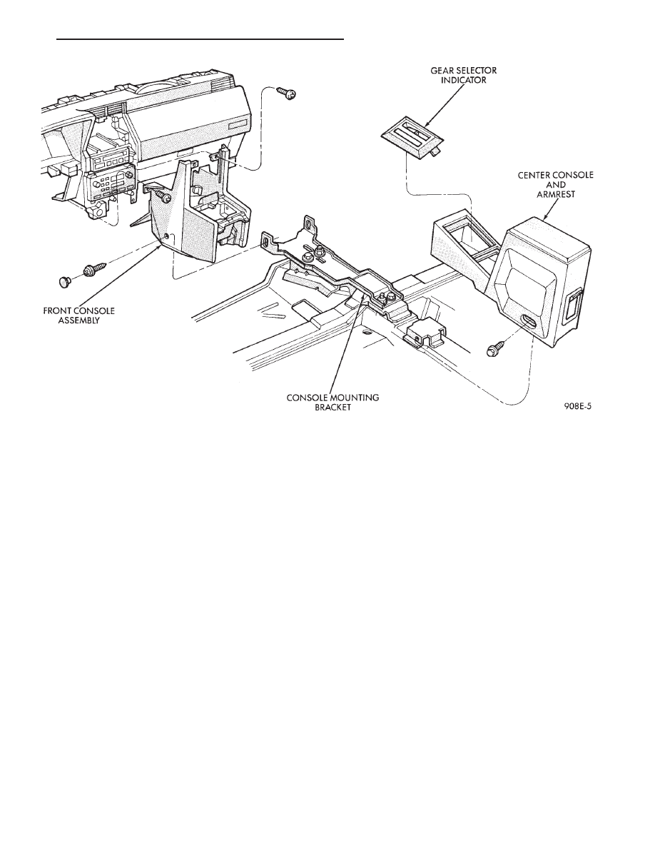
Fig. 27 Front and Center Console with Transmission Range Indicator
Ä
INSTRUMENT PANEL AND GAUGES
8E - 71