Chrysler Le Baron, Dodge Dynasty, Plymouth Acclaim. Manual - part 313


  Index      Chrysler     Chrysler Le Baron, Dodge Dynasty, Plymouth Acclaim - service repair manual 1993 year


Search            


Content   ..  311  312  313  314   ..


Chrysler Le Baron, Dodge Dynasty, Plymouth Acclaim. Manual - part 313


(f) If everything checks out OK, refer to Sending

Unit Test.
(4) With the ignition switch in the ON position,

check for battery voltage across the ignition pin and
the ground pin.

(5) If fuel gauge meets specifications check fuel

tank and original fuel tank sending unit as follows:

(a) Carefully remove fuel tank sending unit from

tank.

(b) Refer to sending unit removal Group 14,

Fuel.

(c) Connect sending unit wire and jumper wire

as described in the test procedure.
(6) If fuel gauge now checks within specifications,

original sending unit is electrically okay, check fol-
lowing as a possible cause:

(a) Ground wire from sending unit to left side

cowl for continuity.

(b) Sending unit deformed. Make sure sending

unit float arm moves freely and pick up tube is not
bent upwards creating an interference with bottom
of tank and inspect float.

(c) Sending unit improperly installed. Install

properly.

(d) Mounting flange on fuel tank for sending

unit deformed. Feel for interference fit of sending
unit to bottom of tank. It is permissible to bend
pick up tube down a little near mounting flange to
gain interference fit.

(e) Fuel tank bottom deformed, causing improper

positioning of sending unit pick up tube. Replace or
repair tank and recheck sending unit.

GAUGE CALIBRATION

(1) Remove the gauge.
(2) Check for ignition voltage and ground to the

gauge.

(3) With the ignition key in the OFF position, re-

place gauge. Turn the ignition key to the ON posi-
tion. To test oil pressure gauge engine must be
running. When testing oil or temperature gauge the
engine should be at normal operating temperature.
Record the gauge position.

(4) Remove gauge and record the resistance be-

tween the sending unit pin and the gauge ground
pin. When checking gauges, it is important to have
the same engine temperature and speed when noting
gauge position. The time between gauge reading and
measuring should be kept to a minimum.

(5) Resistance Chart (Fig. 11), is general guide-

lines for checking the gauge position against the
sending unit resistance.

Because of only a few specific points of gauge posi-

tion versus sending unit resistance, a good estimate
is needed when the resistance falls between gradua-
tions. Even when the resistance corresponds to grad-
uations, the gauge has a tolerance of

6 4 ohms.

Volt gauge: The calibration dot on the volt gauge

corresponds to 13 volts between the gauge ignition
and ground pins. If voltage varies from this, estimate
proper gauge position with input voltage.

FUEL GAUGE REPLACEMENT

(1) Remove instrument cluster bezel.
(2) Remove mask and lens.
(3) If equipped with tachometer, remove three re-

taining screws and pull the tach straight back.

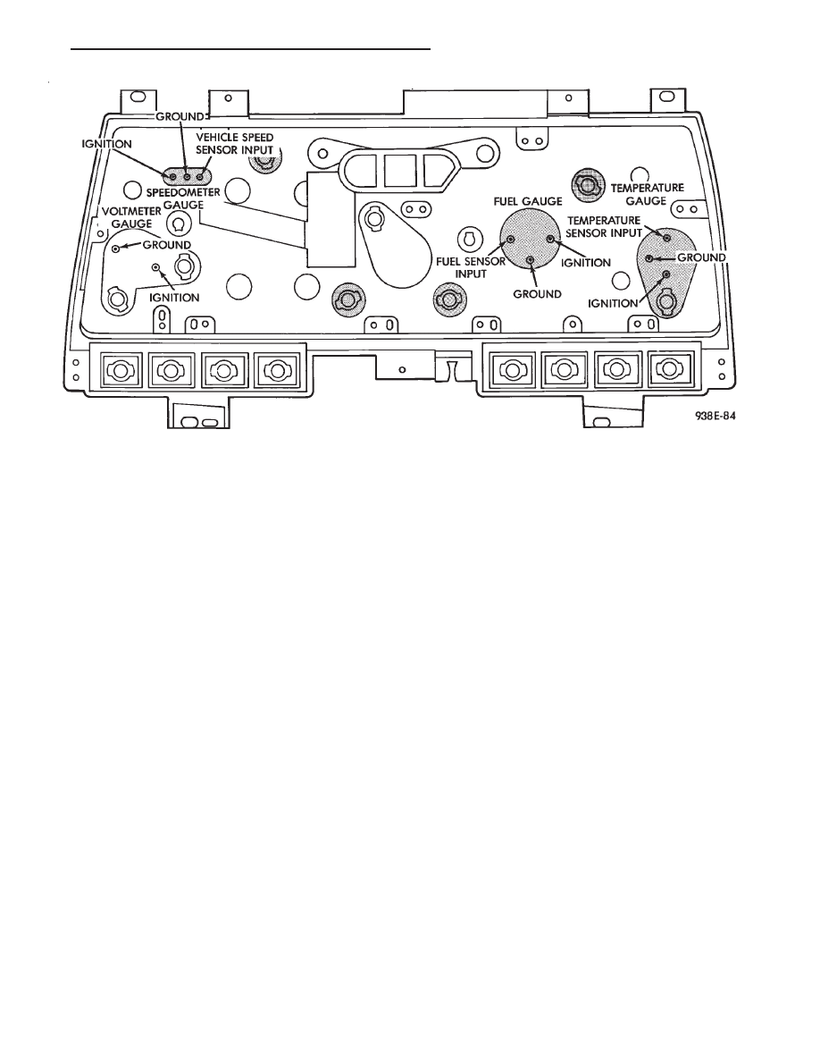
Fig. 10 Instrument Cluster Without Tachometer

Ä

INSTRUMENT PANEL AND GAUGES

8E - 63

(4) Remove two retaining screws and pull fuel

gauge straight back.

(5) For installation reverse above procedures.

TEMPERATURE GAUGE REPLACEMENT

(1) Remove instrument cluster bezel (Fig. 7).
(2) Remove mask and lens.
(3) Remove two retaining screws and pull temper-

ature gauge straight back.

(4) For installation reverse above procedures.

VOLTMETER REPLACEMENT

(1) Remove instrument cluster bezel (Fig. 7).
(2) Remove mask and lens.
(3) Remove three speedometer retaining screws

and pull the speedometer straight back and set aside.

(4) Remove two voltmeter retaining screws and

pull voltmeter straight back.

(5) For installation, place voltmeter on gauge pins

and push until gauge is securely seated in cluster
and reverse above procedures.

TACHOMETER REPLACEMENT

(1) Remove instrument cluster bezel.
(2) Remove mask and lens.
(3) Remove three retaining screws and pull ta-

chometer straight back.

(4) For installation, place tachometer on gauge

pins and push until gauge is securely seated in clus-

ter and reverse above procedures.

TACHOMETER CIRCUIT TESTING

(1) Remove cluster.
(2) Check for battery voltage at cavity J if instru-

ment cluster gray connector.

(3) With the ignition in the ON position, check for

battery voltage at cavity K of the instrument cluster
gray connector (Fig. 8).

(4) Check cavity F of the instrument cluster red

connector for continuity to ground (Fig. 8).

(5) Check for tachometer signal from the power-

train control module by connecting an AC DIGITAL
VOLTMETER to cavity H of the instrument cluster
gray connector and ground. A reading of at least 1.0
volts should be present with the engine running.

(a) If voltage is within specification, go to step 7.
(b) If voltage is NOT within specification, per-

form steps 5 and 6.
(6) If there is less than 1.0 volts at cavity H check

for continuity between cavity H of the instrument
cluster and pin 43 of the powertrain control module
connector (Fig. 12). Also, check the connector at the
powertrain control module for damaged pins or ter-
minal push outs.

(7) If voltage is less than 1.0 volts at cavity H and

there is continuity between cavity H of the instru-

Fig. 11 Gauge Resistance

8E - 64

INSTRUMENT PANEL AND GAUGES

Ä

ment cluster and pin 43 of the powertrain control
module connector, replace the powertrain control
module.

(8) If all tests performed test good replace the ta-

chometer drive module.

(9) If the tachometer continues to be inoperative,

replace the tachometer assembly.

TACHOMETER DRIVE MODULE
REPLACEMENT

(1) Remove instrument cluster (Fig. 13).

(2) Remove drive module by pivoting upward from

printed circuit board and pulling away from locating
notches.

(3) For installation, position module on locating

notches and push down securely over printed circuit
board and reverse above procedures.

SPEEDOMETER SYSTEM

AP-body vehicles are equipped with electronically

driven speedometer and odometer assemblies. The
unit has the same appearance as a conventional
speedometer but it eliminates the cable-driven me-
chanical system. A signal is sent from a transmis-

sion-mounted

speed

sensor

to

the

speedometer

circuitry through the wiring harness. By eliminating
the speedometer cable, instrument cluster service
and removal is improved. Refer to Fig. 14 Speedom-
eter Diagnosis.

When the speedometer is out of calibration. The

electronic automatic transaxle vehicle speed sensor
output must be calibrated to reflect the different
combinations of equipment. The procedure is called
Pinion Factor, refer to Group 21, Transaxle for the
procedure.

SPEEDOMETER/ODOMETER ASSEMBLY
REPLACEMENT

(1) Remove cluster bezel.
(2) Remove cluster mask and lens.
(3) Remove tachometer. If equipped.
(4) Remove fuel gauge.
(5) Remove three screws attaching speedometer/

odometer assembly to the cluster housing.

(6) Pull speedometer rearward to remove from

cluster housing.

(7) For installation reverse above procedures.

VEHICLE SPEED SENSOR REPLACEMENT

(1) Remove harness connector from sensor and

make sure weather seal is on harness connector.

(2) Remove sensor retaining bolt.
(3) Pull sensor and pinion gear assembly out of

transaxle. If necessary, carefully pry loose with a flat
blade screwdriver (Fig. 15 and 16).

(4) For installation reverse above procedures and

seat sensor assembly by hand to insure proper gear
engagement. Tighten retaining bolt to 7 N

Im (60 in.

lbs.) torque.

ELECTRONIC AUTOMATIC TRANSAXLE
VEHICLE SPEED SENSOR REPLACEMENT

The output vehicle speed sensor is located to the

left of the manual shift lever.

(1) Raise and support vehicle on safety stands.
(2) Remove vehicle speed sensor (Fig. 17).
(3) For installation, reverse above procedures.

Fig. 12 Powertrain Control Module Pin Location

Fig. 13 Tachometer Drive Module

Ä

INSTRUMENT PANEL AND GAUGES

8E - 65

Fig. 14 Speedometer System Diagnosis

Fig. 15 Vehicle Speed Sensor and Connector

Fig. 16 Vehicle Speed Sensor and Speedometer

Pinion

8E - 66

INSTRUMENT PANEL AND GAUGES

Ä


Content   ..  311  312  313  314   ..