Chrysler Le Baron, Dodge Dynasty, Plymouth Acclaim. Manual - part 312


  Index      Chrysler     Chrysler Le Baron, Dodge Dynasty, Plymouth Acclaim - service repair manual 1993 year


Search            


Content   ..  310  311  312  313   ..


Chrysler Le Baron, Dodge Dynasty, Plymouth Acclaim. Manual - part 312


FUEL TANK SENDING UNIT TEST

Refer to Group 14, Fuel for test procedures.

LOW OIL PRESSURE WARNING LAMP TEST

The low oil pressure warning lamp will illuminate

when the ignition key is turned to the ON position
without engine running. The lamp also illuminates
should the engine oil pressure drop below a safe oil
pressure level.

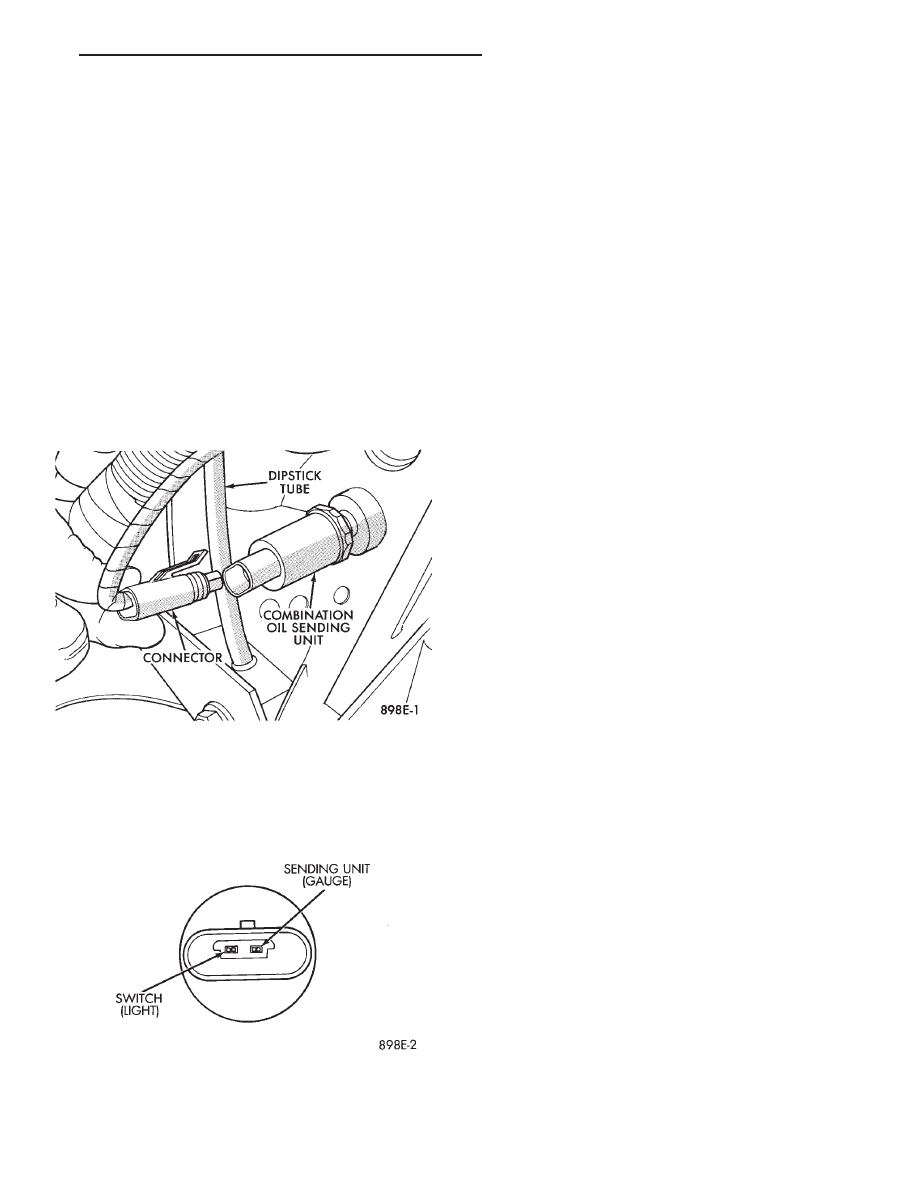
To test the system turn ignition key to the ON po-

sition. If the lamp fails to light, inspect for a broken
or disconnected wire at the oil pressure combination
unit, located at the front of the engine (Fig. 3). If the
wire at the connector checks good, pull connector
loose from the switch and with a jumper wire ground
connector to the engine. With the ignition key turned
to the ON position check the warning lamp. If lamp
still fails to light, inspect for a burned out lamp or
disconnected socket in the cluster.

COMBINATION OIL SENDING UNIT TEST

The combination oil sending unit has two func-

tions:

(1) The normal closed circuit keeps the oil pressure

warning lamp on until there is oil pressure (Fig. 4).

(2) The sending unit provides a resistance that

varies with oil pressure.

To test the normally closed oil lamp circuit, discon-

nect the locking connector and measure the resis-
tance between the switch terminal and the metal
housing. The ohmmeter should read continuity. Start
the engine.

If there is oil pressure, the ohmmeter should read

an open circuit.

To test the sending unit, measure the resistance

between the sending unit terminal and the metal
housing. The ohmmeter should no continuity. Start
the engine.

The ohmmeter should read between 30 to 55 ohms,

depending on engine speed, oil temperature and oil
viscosity.

If the above results are not obtained, replace the

sending unit.

SEAT BELT WARNING SYSTEM

For testing of this system refer to Group 8M, Re-

straint Systems.

AIR BAG WARNING SYSTEM

For testing of this system refer to Group 8M, Re-

straint Systems.

MALFUNCTION INDICATOR (CHECK ENGINE)
SYSTEM

For testing of this system using DRB II, refer to

the Body Powertrain Diagnostic Procedures.

BRAKE SYSTEM WARNING LAMP TEST

The brake warning lamp illuminates when parking

brake is applied with ignition key turned ON. The
same lamp will also illuminate should one of the two
service brake systems fail when brake pedal is ap-
plied. Refer to Brake system warning Lamp Diagno-
sis (Fig. 5).

To test system turn ignition key ON and apply

parking brake. If lamp fails to light, inspect for a
burned out lamp, disconnected socket, a broken or
disconnected wire at switch. The lamp also lights
when the ignition switch is turned to start.

To test service brake warning system, raise vehicle

on a hoist and open a wheel cylinder bleeder while a
helper depresses brake pedal and observes warning
lamp. If lamp fails to light, inspect for a burned out
lamp, disconnected socket, a broken or disconnected
wire at switch.

If lamp is not burned out and wire continuity is

proven, replace brake warning switch in brake line
Tee fitting mounted on frame rail in engine compart-
ment below master cylinder (Fig. 6).

CAUTION: If wheel cylinder bleeder was opened
check master cylinder fluid level.

Fig. 3 Combination Oil Sending Unit

Fig. 4 Combination Oil Sending Unit Test

Ä

INSTRUMENT PANEL AND GAUGES

8E - 59

CLUSTER BEZEL REPLACEMENT

(1) Remove four screws holding bezel to instru-

ment panel (Fig. 7).

(2) Remove bezel over steering wheel.

(3) For installation reverse above procedures.

CLUSTER MASK AND LENS

REMOVAL

(1) Remove instrument cluster bezel.
(2) Remove five screws holding mask and lens to

cluster.

(3) Remove mask and lens.
(4) For installation reverse above procedures.

CLUSTER ASSEMBLY REPLACEMENT

(1) Disconnect battery to assure no Air Bag Sys-

tem fault codes are stored.

(2) Remove cluster bezel (Fig. 7).
(3) Remove the upper steering column cover.
(4) Remove the four screws attaching cluster hous-

ing to the base panel.

(5) Pull cluster rearward, reach behind cluster and

disconnect the two wiring harnesses.

(6) Remove cluster assembly.

INSTALLATION

(1) Connect wiring harnesses.
(2) Position cluster and secure to base panel with

four screws.

(3) Install upper and lower steering column cover.
(4) Install cluster bezel.

Fig. 5 Brake System Warning Lamp Diagnosis

Fig. 6 Brake Warning Lamp Switch

8E - 60

INSTRUMENT PANEL AND GAUGES

Ä

(5) Reconnect battery.

GAUGES

CAUTION:

During

the

removal

and

installation

watch overlays are not damage.

It is not necessary to remove instrument cluster

from vehicle for gauge replacement.

When removing gauge assemblies from cluster,

gauge must be pulled straight out, not twisted, or
damage to gauge pins may result.

MULTIPLE GAUGE INOPERATIVE

Volt, speedometer, tachometer and other gauges

appear to malfunction. Also check warning indicator
lamps:

(1) Remove cluster
(2) Check for ignition voltage at pin E of the red

connector. If no voltage, repair as necessary (Fig. 8).

(3) Check for ground continuity between pin C of

the gray connector. If no ground, repair as necessary.

(4) If voltage and ground OK and pins or connec-

tors are not distorted, replace printed circuit board.

(5) Install cluster.

SINGLE GAUGE INOPERATIVE (FIG. 9 AND
10)

(1) Remove gauge in question.

(2) With the ignition key ON, check for ignition

voltage at ignition pin of gauge. Check for ground at
ground pin of gauge.

(a) If no voltage or ground, remove cluster and

check pin E red connector for ignition voltage or
pin C gray connector for ground (Fig. 8).

(b) If no voltage or ground, repair as necessary.

Refer to 8W, Wiring Diagrams.

(c) If there is voltage or ground, check cluster for

distorted terminals. If terminals are OK, replace
printed circuit board.
(3) When testing the temperature gauge, allow the

engine to run until the vehicle reaches a normal op-
erating temperature. Turn ignition OFF and remove
gauge from cluster.
• When checking the temperature and oil pressure
gauges, it is important to have the same engine tem-
perature and engine speed when noting gauge posi-
tion.
• The time between gauge position reading and
sending unit measuring should be kept to a mini-
mum.
• When testing oil pressure gauge, engine needs to
be running.

(a) Measure and record the resistance between

sending unit pin and ground pin of the gauge in
question. Refer to Gauge Calibration.

Fig. 7 Upper Instrument Panel Components

Ä

INSTRUMENT PANEL AND GAUGES

8E - 61

(b) If resistance and gauge position are not sim-

ilar, replace gauge.

(c) If OK, test resistance from the sending unit

to the cluster connector.

(d) If reading is different from the first resis-

tance measured, check printed circuit board for
contact to cluster connector.

(e) If OK and contacts are not distorted, replace

printed circuit board.

Fig. 8 Printed Circuit Board Connector

Fig. 9 Instrument Cluster With Tachometer

8E - 62

INSTRUMENT PANEL AND GAUGES

Ä


Content   ..  310  311  312  313   ..