Chrysler Le Baron, Dodge Dynasty, Plymouth Acclaim. Manual - part 310


  Index      Chrysler     Chrysler Le Baron, Dodge Dynasty, Plymouth Acclaim - service repair manual 1993 year


Search            


Content   ..  308  309  310  311   ..


Chrysler Le Baron, Dodge Dynasty, Plymouth Acclaim. Manual - part 310


Perform cluster Self Diagnostic Test to determine

whether problem is within cluster or outside of clus-
ter.

Refer to Fig. 24 and 25.
Successful completion of the SELF DIAGNOSTIC

TEST indicates that the problem is in the wiring,
connectors or sensors out side of the cluster.

CLUSTER ASSEMBLY REMOVAL

The electronic cluster which is serviced as an as-

sembly is removed with the same procedure as the
conventional cluster.

CONDITION: CLUSTER DISPLAYS DO NOT
ILLUMINATE AFTER VEHICLE IS STARTED

(1) Check fuses and verify battery and ignition

voltage at cluster connector.

(2) Check ground from cluster connector to instru-

ment panel ground stud.

SWITCH AND PANEL COMPONENT SERVICE

HEADLAMP SWITCH

The headlamp switch is located on the left side of

the switch pod. The switch controls the headlamps,
parking lamps, fog lamps and instrument light dim-

ming. If any of the switches require replacement the
entire headlamp switch assembly must be replaced
(Fig. 26 and 27).

REMOVAL

(1) Remove switch pod assembly from the instru-

ment panel. DO NOT attempt to remove instrument
cluster dimmer switch or wiper delay switch knob,
they are not removable.

(2) Remove turn signal switch lever by pulling

straight out of switch pod.

(3) Remove screws from bottom of switch pod.
(4) Separate inner and outer switch pod halves and

remove turn signal switch to gain access to screw.

(5) Remove five inner switch pod panel screws and

3 screws from underneath the switch pod. Separate
the inner bezel from the outer bezel.

(6) Remove switch mounting screws before discon-

necting linkage.

(7) Disconnect switch linkage from buttons. Pull

the linkage straight up from the switch/button to dis-
engage it and remove switch.

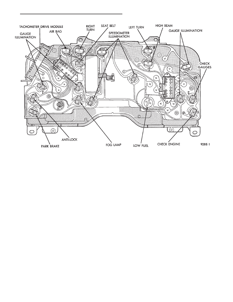
Fig. 23 Mechanical Cluster Lamp Location

Ä

INSTRUMENT PANEL AND GAUGES

8E - 51

Fig. 24 Electronic Cluster Self-Diagnostic Test

8E - 52

INSTRUMENT PANEL AND GAUGES

Ä

Fig. 25 Electronic Cluster Self-Diagnostic Test—Continued

Ä

INSTRUMENT PANEL AND GAUGES

8E - 53

INSTALLATION

(1) Latch switch linkage in the up position.
(2) Insert dimmer shaft into dimmer knob while

aligning switch in to switch pod assembly.

(3) Install switch attaching screws.
(4) Unlatch linkage and install onto push buttons.
(5) Operate all switch modes for correct operation.
(6) Install turn signal switch.
(7) Reconnect wiring for turn signal switch, mak-

ing sure wire is properly clipped into position.

(8) Place together the inner and outer bezels. In-

stall five inner switch pod panel screws and three
screws from underneath the switch pod.

(9) Install turn signal lever by pushing straight

into switch assembly.

(10) Install switch pod assembly.

LOWER STEERING COLUMN COVER
REMOVAL

(1) Remove screws along top edge of cover.
(2) Remove screw at each lower corner of cover.

(3) Remove cover from underneath over column

cover.

(4) For installation reverse above procedures.

GLOVEBOX MODULE REMOVAL

(1) Disconnect battery negative cable and isolate

or remove fuse #26 prior to removing switch or wires
may short to ground.

(2) Remove cowl side trim panel.
(3) Remove screws at right end of glovebox and

lower corners.

(4) Open glovebox, remove light and disconnect

wiring.

(5) Remove five screws along top of glovebox frame

and screw at each lower corner.

(6) Remove glovebox assembly.
(7) For installation reverse above procedures.

CONCEALED HEADLAMP MODULE REMOVAL

(1) Remove left under panel silencer.
(2) Slide module off bayonet bracket while disen-

gaging spring retainer.

(3) Disconnect wiring terminal.
(4) For installation reverse above procedures.

HOOD RELEASE REMOVE

(1) Remove lower column cover.
(2) Remove screws on fuse block and move aside.
(3) Remove screws on hood release assembly to re-

move.

(4) For installation reverse above procedures.

AIR CONDITIONING CONTROL REMOVE

(1) Remove center stack bezel.
(2) Remove two control mounting screws (Fig. 28

and 29).

(3) Slide control rearward, disconnect cable, vac-

uum harness, and electrical wiring. With automatic
temperature control, disconnect wiring connector; be-
ing careful not to break off locking tab.

(4) For installation reverse above procedures.

Fig. 26 Switch Pod Assembly

Fig. 27 Headlamp Multi-Function Switch

Fig. 28 A/C Control

8E - 54

INSTRUMENT PANEL AND GAUGES

Ä


Content   ..  308  309  310  311   ..