Chrysler Le Baron, Dodge Dynasty, Plymouth Acclaim. Manual - part 308
ELECTRONIC DIGITAL CLOCK
The electronic digital clock is in the radio. The
clock and radio each use the display panel built into
the radio. A digital readout indicates the time in
hours and minutes whenever the ignition switch is in
the ON or ACC position.
When the ignition switch is in the ON or OFF po-
sition, or when the radio frequency is being dis-
played, time keeping is accurately maintained.
The procedure for setting the clock varies slightly
with each radio. The correct procedure is described
under the individual radio operating instructions re-
ferred to in the Owner’s manual supplied with the
vehicle.
WARNING LAMPS
The AG & AJ Body instrument clusters have warn-
ing lamps or indicators with the electronic cluster for
six different systems. These include low oil pressure,
check gauges, brake system, air bag, seat belt, mal-
function indicator (check engine) lamp.
CLUSTER AND GAUGE SERVICE AND TESTING
CAUTION: Disconnect negative battery cable, in en-
gine
compartment,
before
servicing
instrument
panel. When power is required for test purposes,
reconnect battery cable for test only.
Disconnect negative battery cable after test and be-
fore continuing service procedures.
It is not necessary to remove instrument cluster
from vehicle for gauge replacement.
Gauges must be pulled straight out, when remov-
ing or pins may be damaged.
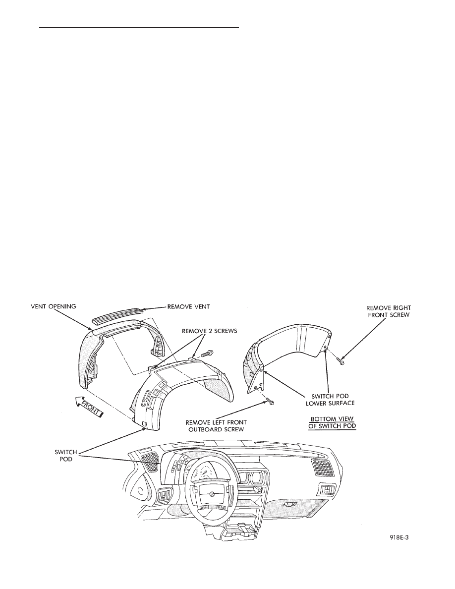
SWITCH POD ASSEMBLY REMOVAL
(1) Disconnect negative battery cable.
(2) Pry up edge of panel vent grille, using a
straight flat edge tool to disengage clips, then re-
move grille (Fig. 4).
(3) Remove two screws located under panel vent
grille.
(4) Remove two screws underneath switch POD as-
sembly.
(5) With tilt steering adjust steering wheel to the
lowest setting.
(6) Pull switch module rearward to remove module
and disconnect all wire connections.
(7) For
Installation
reverse
above
procedures.
Tighten all screws to 2 N
Im (20 in. lbs.) torque.
MECHANICAL/ELECTRONIC CLUSTER REMOVAL
CLUSTER MASK AND LENS REMOVAL
(1) Remove switch pod assembly (Fig. 4).
(2) Remove tilt column lever if equipped.
(3) Remove steering column trim cover.
Fig. 4 Switch POD Assembly
Ä
INSTRUMENT PANEL AND GAUGES
8E - 43