Chrysler Le Baron, Dodge Dynasty, Plymouth Acclaim. Manual - part 303
AC AND AY BODIES
INDEX
page
page
Electronic Cluster
. . . . . . . . . . . . . . . . . . . . . . . . 34
Gauges
. . . . . . . . . . . . . . . . . . . . . . . . . . . . . . . . 28
General Information
. . . . . . . . . . . . . . . . . . . . . . . 23
Interior Lamp Replacement
. . . . . . . . . . . . . . . . . 41
Mechanical Cluster and Gauge Service
. . . . . . . . 24
Mechanical/Electronic Cluster Removal
. . . . . . . . 25
Switch and Panel Component Service
. . . . . . . . . 37
GENERAL INFORMATION
MECHANICAL CLUSTER
The mechanical cluster includes a fuel, oil pres-
sure, coolant temperature, and voltmeter gauges. All
incorporate magnetic type gauges. When the ignition
switch is in the OFF position, the gauges will show a
reading; however, the readings are only accurate
when the ignition switch is in the ON position.
The mechanical cluster also includes an electric
speedometer, driven by pulses from the vehicle speed
sensor (Fig. 1).
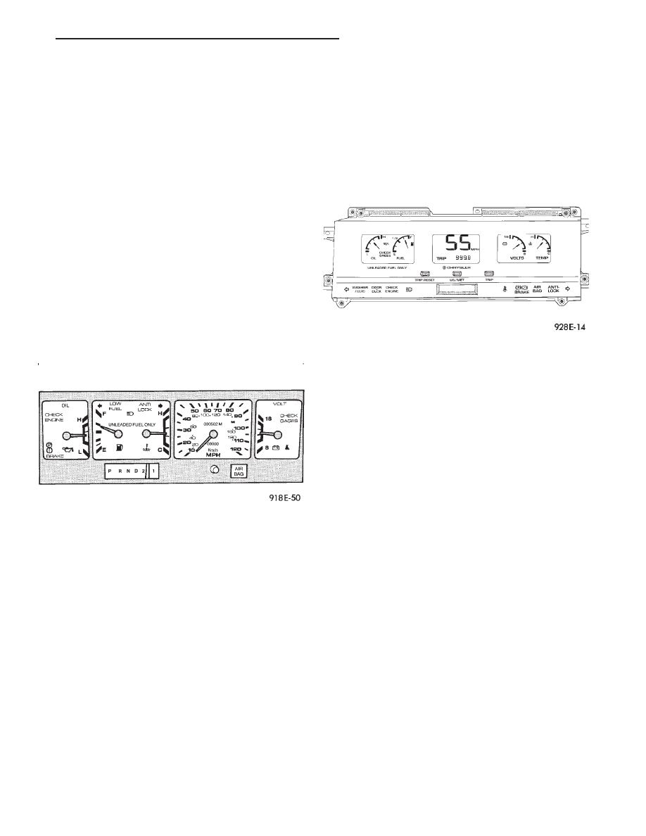
ELECTRONIC CLUSTER
The electronic cluster is easily distinguished from
the mechanical cluster by its digital and linear dis-
play. The electronic cluster includes:
• Oil pressure gauge
• Coolant temperature gauge
• Voltmeter
• Fuel gauge
The electronic cluster receives virtually all of its
information to display from the body controller and
powertrain control module via the Chrysler Collision
Detection (CCD) Serial Data Bus. The odometer
memory is no longer retained in the cluster. This is
now retained in the body controller (Fig. 2).
ELECTRONIC CLUSTER DIMMING
The electronic cluster display is dimmed from day-
time to night time intensity when the headlamp
switch is turned on. This intensity can be controlled
using the headlamp switch rheostat.
An additional detent on the headlamp switch rheo-
stat will allow daytime intensity while driving with
headlamps on during the daytime.
WARNING LAMPS
The mechanical instrument cluster will have warn-
ing lamps for six systems. These include brake sys-
tem, air bag, seat belt, low fuel, anti-lock for optional
anti-lock brake system, and malfunction indicator
(check engine) lamp. The cluster also includes check
gages indicator which will illuminate in a warning
situation. This will notify driver to check for a prob-
lem in coolant temperature, oil pressure, or electrical
systems.
The electronic cluster will have warning indicator
lamps for eight different systems. These include:
• Air Bag
• Low washer fluid
• Door/deck lid ajar
• Malfunction Indicator (Check engine) Lamp
• Brake system
• Seat belt
• Anti-lock (ABS) for optional anti-lock brake sys-
tem
• Check gages, monitors engine coolant, oil pressure
and electrical charging system failures.
In addition, ISO symbol will flash to notify the
driver in event of:
• Low fuel
• High temperature
• Low oil pressure
• Charging system failure
Fig. 1 Mechanical Cluster
Fig. 2 Electronic Cluster
Ä
INSTRUMENT PANEL AND GAUGES
8E - 23