Chrysler Le Baron, Dodge Dynasty, Plymouth Acclaim. Manual - part 301
CONDITION: SPEEDOMETER AND ODOMETER
ARE INOPERATIVE OR OPERATES
INTERMITTENTLY
PROCEDURE
Check for defective vehicle speed sensor wiring.
CONDITION: OIL GAUGE, FUEL GAUGE,
TEMPERATURE GAUGE, OR VOLTAGE GAUGE
INOPERATIVE
PROCEDURE
Check for defective sending unit or wiring:
(a) Sending units and wiring can be checked by
grounding the connector leads, at the sending unit,
in the vehicle.
(b) With the ignition in the ON position, a
grounded input will cause the oil, fuel, or temper-
ature gauge to read maximum.
CONDITION: CLUSTER DISPLAY DOES NOT
DIM WHEN HEADLAMP SWITCH IS
ACTIVATED AND RHEOSTAT ROTATED
PROCEDURE
(1) Check fuses in headlamp circuit.
(2) Check for loose connections or defective wiring
from headlamp switch to the cluster.
(3) Check for defective headlamp switch.
(4) The electronic instrument cluster requires both
a marker feed and illumination feed to operate cor-
rectly.
SWITCH AND PANEL COMPONENT SERVICE
HEADLAMP/FOG LAMP SWITCH
REPLACEMENT
(1) Remove cluster bezel (Fig. 40).
(2) Remove three screws securing headlamp switch
mounting plate to base panel (Fig. 41).
(3) Pull headlamp/fog lamp switch mounting plate
rearward. Disconnect wiring connectors from head-
lamp switch and fog lamp switch pigtail (Fig. 42).
(4) Remove knob and stem by depressing button on
bottom of the switch (Fig. 43).
(5) Snap-out escutcheon.
(6) Remove fog lamp switch from escutcheon.
(7) Remove nut that attaches headlamp switch to
mounting plate (Fig. 44).
(8) For installation reverse above procedures.
FOG LAMP SWITCH TEST
(1) Remove the fog lamp switch from mounting lo-
cation.
(2) Disconnect the wiring harness from the switch
pigtail.
(3) Using a Ohmmeter, test for continuity between
the terminals of the switch pigtail (Fig. 45).
(4) If not OK, replace switch.
LOWER STEERING COLUMN COVER
REPLACEMENT
(1) Disconnect park brake release rod from park
brake.
(2) Remove fuse box access door and remove screw
from lower column cover (Fig. 46).
(3) Remove screws from lower cover, four across
the top and two on bottom.
(4) Remove lower steering column cover.
(5) For installation reverse above procedures.
LEFT LOWER INSTRUMENT PANEL SILENCER
REPLACEMENT
(1) Remove screws from front of silencer (Fig. 47).
(2) Remove push nut.
(3) Remove silencer.
(4) For installation reverse above procedures.
RIGHT LOWER INSTRUMENT PANEL
SILENCER REPLACEMENT
(1) On floor shift vehicles, remove console assem-
bly and center brace bracket.
(2) On column shift vehicles, remove center brace
bracket.
(3) Remove screws from front of silencer (Fig. 47).
(4) Remove three push nuts from rear of silencer.
(5) Remove lower right silencer.
(6) For installation reverse above procedures.
GLOVE BOX ASSEMBLY REPLACEMENT
(1) Disconnect battery negative cable and isolate
or remove fuse #2 prior to removing switch or wires
may short to ground.
(2) Open glove box door and disconnect check
strap.
(3) Remove glove box light and switch by squeez-
ing retaining tabs from behind switch mount and
slide rearward. Disconnect wiring connectors.
(4) Remove 11 screws from glove box assembly
(Fig. 48).
(5) Remove glove box assembly.
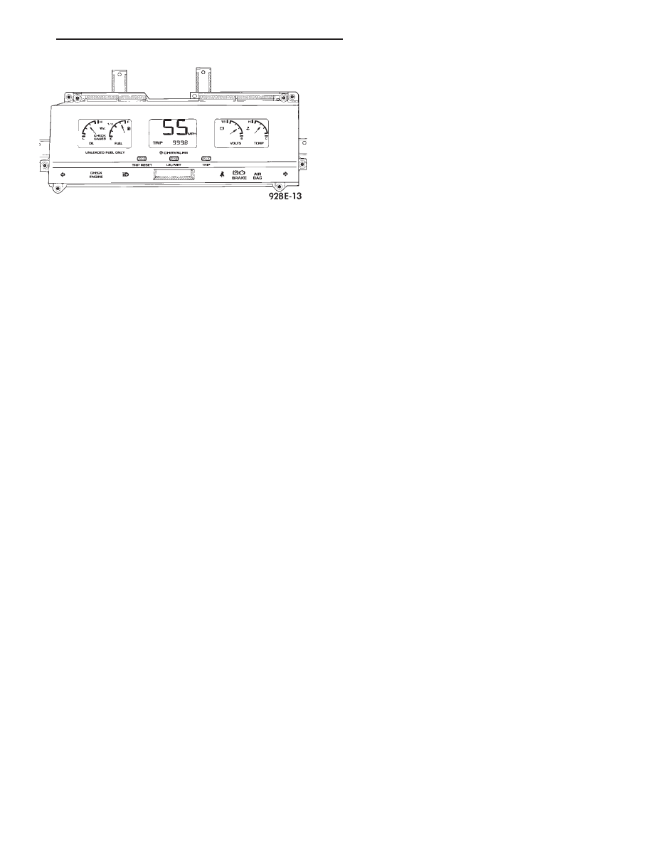
Fig. 36 Electronic Cluster
Ä
INSTRUMENT PANEL AND GAUGES
8E - 15