Chrysler Le Baron, Dodge Dynasty, Plymouth Acclaim. Manual - part 299
(a) Route transmission range indicator guide as-
sembly under left steering column wing and down
left side of column (Fig. 12).
(b) Insert flange of column insert into column,
squeeze legs together with tabs under column
jacket and engage lock bar to secure insert (Fig.
14).
(c) Hook cable eyelet to steering column actuator
check pointer, should indicate neutral. Do not kink
or bind transmission range indicator guide tube
and position guide tube in original location.
(d) Adjust with tool if necessary to center pointer
on N (Neutral) and check in other gears (Fig. 15).
(4) Install upper and lower steering column cover.
(5) Install the rear window defogger bezel and ra-
dio bezel.
(6) Install cluster bezel.
(7) Reconnect battery.
REMOVAL—CLUSTER WITHOUT TRANSMISSION RANGE
INDICATOR FROM STEERING COLUMN
(1) Remove cluster bezel (Fig. 10).
(2) Remove four screws attaching cluster to base
panel.
(3) Pull cluster rearward carefully, reach behind
and disconnect the two harness connectors.
(4) Carefully rotate cluster and remove the two
transmission range indicator screws.
(5) Remove cluster assembly.
(6) For installation reverse above procedures.
(a) Do not kink guide tube when installing clus-
ter.
(b) Replace guide tube behind fuse block.
GAUGES
It is not necessary to remove instrument clus-
ter assembly from vehicle for gauge replace-
ment.
When removing gauge assemblies from cluster,
gauge must be pulled straight out, not twisted, or
damage to gauge pin may result.
MULTIPLE GAUGE MALFUNCTION
If the fuel, voltage and tachometer gauges appear
to be malfunctioning, remove the cluster assembly.
Check for good pin contact between the wire harness
and printed circuit board. If there is good contact,
check for ignition voltage at ignition cavity C of the
black connector. If there is ignition voltage, check for
continuity between the wire harness ground cavity H
of the black connector and ground. If there is conti-
nuity, replace printed circuit board.
If the temperature, oil pressure and speedometer
gauges appear to be malfunctioning remove the clus-
ter assembly. Check for a good contact between the
wire harness and the printed circuit board. If there is
good contact, check for ignition voltage at cavity J of
the red connector. If there is voltage, check for con-
tinuity at cavity H of the black connector. If there is
continuity, replace the printed circuit board.
If the temperature, fuel, voltage and speedometer
gauges appear to be malfunctioning, remove the clus-
ter assembly. Check for good pin contact between the
wire harness and the printed circuit board. If there is
good contact, check ignition voltage at cavity J of the
red connector. If there is voltage, check for continuity
at cavity H of the black connector. If there is conti-
nuity, replace the printed circuit board.
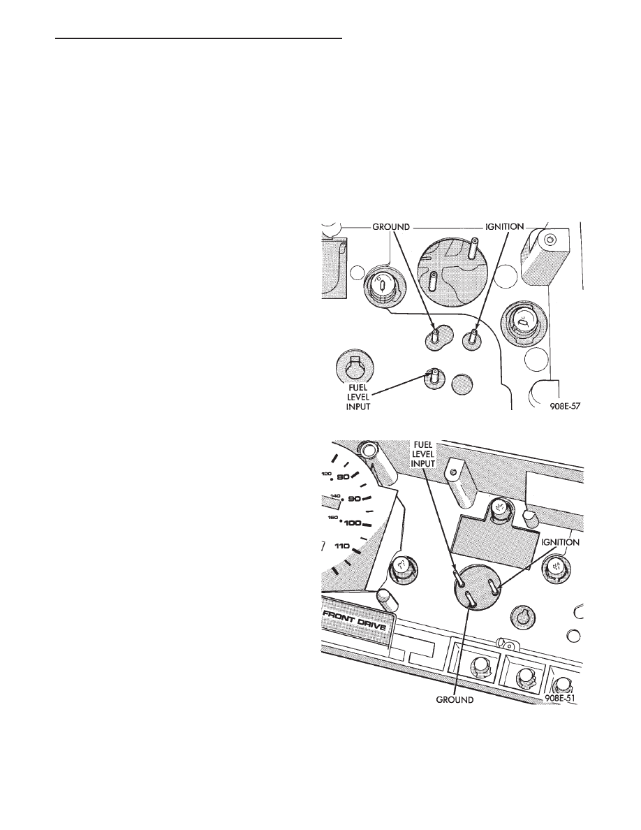
GAUGE INOPERATIVE (FIG. 17 THROUGH 23)
(1) Remove gauge in question.
Fig. 17 Fuel Gauge Pins—With Tachometer
Fig. 18 Fuel Gauge Pins—Without Tachometer
Ä
INSTRUMENT PANEL AND GAUGES
8E - 7