Chrysler Le Baron, Dodge Dynasty, Plymouth Acclaim. Manual - part 302


  Index      Chrysler     Chrysler Le Baron, Dodge Dynasty, Plymouth Acclaim - service repair manual 1993 year


Search            


Content   ..  300  301  302  303   ..


Chrysler Le Baron, Dodge Dynasty, Plymouth Acclaim. Manual - part 302


(2) Remove glove box assembly (Fig. 49). Refer to

Glove Box Assembly Replacement.

(3) Remove screw from relay.
(4) Disconnect wiring.
(5) Remove relay.

(6) For installation reverse above procedures.

REAR WINDOW DEFOGGER SWITCH
REPLACEMENT

(1) Remove left bezel by pulling straight back.
(2) Press tabs and pull switch rearward.
(3) Disconnect wiring and remove switch.
(4) For installation reverse above procedures.

INSTRUMENT PANEL CENTER BEZEL
REPLACEMENT

(1) Pull bezel straight back disengaging five clips.
(2) Disconnect ash receiver lamp and wiring from

bezel.

(3) For installation reverse above procedures.

ASH RECEIVER/CUP HOLDER REPLACEMENT

(1) Remove center bezel. Disconnect ash receiver

lamp socket.

(2) Remove four screws from center module and re-

move module.

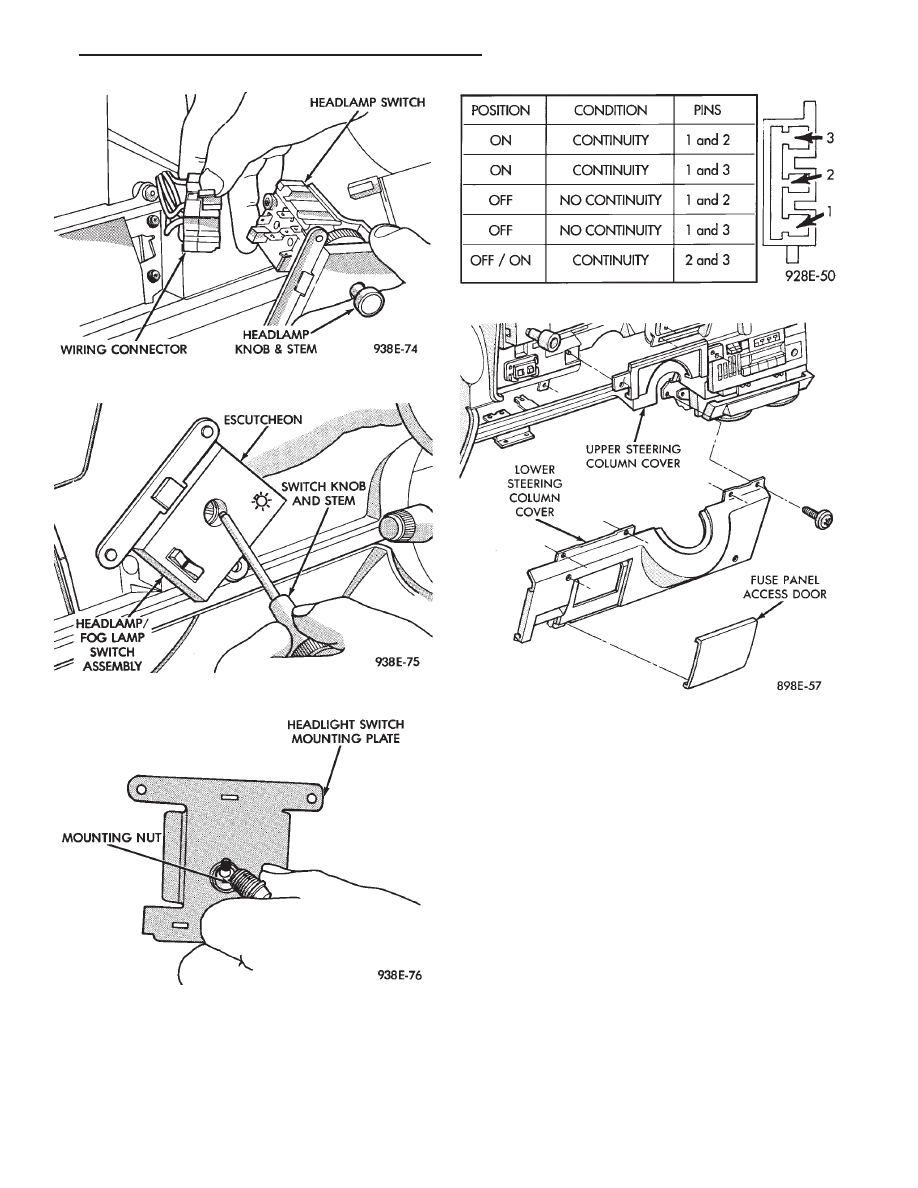
Fig. 42 Headlamp Switch Wiring Connectors

Fig. 43 Headlamp Switch Knob and Stem

Fig. 44 Headlamp Switch Mounting Nut

Fig. 45 Fog Lamp Switch Test

Fig. 46 Lower Steering Column Cover

Ä

INSTRUMENT PANEL AND GAUGES

8E - 19

Fig. 47 Instrument Panel Silencers

Fig. 48 Glove Box Assembly

Fig. 49 Fog Lamp Relay

8E - 20

INSTRUMENT PANEL AND GAUGES

Ä

(3) Remove four screws from ash receiver/cup

holder housing.

(4) For installation reverse above procedures.

AIR CONDITIONING CONTROL
REPLACEMENT

(1) Disconnect battery negative cable and isolate

or remove fuse #2 prior to removing switch or wires
may short to ground.

(2) Remove center bezel. Disconnect ash receiver

lamp socket.

(3) Remove glove box assembly. Refer to Glove Box

Assembly Replacement.

(4) Reach through glove box opening and discon-

nect vacuum lines.

(5) Remove two control mounting screws (Fig. 50).

(6) Slide control rearward, disconnect cable, and

electrical wiring.

(7) Remove unit.
(8) For installation reverse above procedures.

CIGAR LIGHTER ASSEMBLY REPLACEMENT

(1) Remove center bezel. Disconnect ash receiver

lamp socket.

(2) Remove two screws from bezel of the lighter as-

sembly.

(3) Pull assembly rearward and disconnect wiring.
(4) For installation reverse above procedures.

TRAVELER/MESSAGE CENTER
REPLACEMENT

(1) Remove cluster bezel.
(2) Remove four mounting screws.
(3) Pull unit rearward and disconnect wiring.
(4) For installation reverse above procedures.

INSTRUMENT PANEL

INSTRUMENT PANEL TOP COVER
REPLACEMENT

(1) Lift up rearward edge of instrument panel top

cover.

(2) Pull panel rearward to remove.
(3) To install: position top cover and snap into

place, pull rearward for proper fit.

INSTRUMENT PANEL REPLACEMENT

CAUTION: Disconnect negative battery cable, in en-
gine

compartment,

before

servicing

instrument

panel.

(1) Disconnect battery negative cable and isolate

or remove fuse #2 prior to removing switch or wires
may short to ground.

(2) Remove left and right A-pillar trim.
(3) Remove left and right cowl side trim.
(4) Remove glove box assembly. Refer to Glove Box

Assembly Replacement.

(5) Remove four relays above glove box assembly.
(6) Reach through glove box opening and discon-

nect A/C control vacuum lines, radio noise suppressor
wires, and blower motor/cycling switch wires.

(7) Remove hood release handle.
(8) Remove lower steering column cover.
(9) Remove lower left instrument panel silencer

and reinforcement.

(10) Remove instrument panel center bezel.
(11) Remove floor console. Refer to Group 23,

Body.

(12) Remove radio, A/C control, cigar lighter, and

message center/traveler.

(13) Disconnect demister hoses.
(14) Remove instrument panel top cover (Fig. 51).
(15) Disconnect battery to assure no air bag sys-

tem fault codes are stored.

(16) Remove cluster refer to Cluster Assembly.
(17) Remove radio and rear window defogger be-

zels.

(18) Lower steering column.
(19) Loosen instrument panel pivot bolts.
(20) Remove screws which attach instrument panel

to windshield fence line.

(21) Allow panel to roll down slightly and discon-

nect remaining electrical connections.

(22) With the aid of a helper remove panel pivot

bolts and remove panel from vehicle.

(23) For installation reverse above procedures.

INTERIOR LAMP REPLACEMENT

The dome, overhead console and door lamps, if

equipped operate when the doors are open or head-
lamp switch is placed in courtesy position. The front
header reading lamp operates only when the lamp
push buttons are ON.

DOME LAMP

Pry either the forward or rearward edge of the lens

away from the bezel and replace lamp.

FRONT HEADER READING LAMP

Pull lamp from headliner. Disconnect wiring and

replace lamp.

Fig. 50 A/C Control

Ä

INSTRUMENT PANEL AND GAUGES

8E - 21

DOOR LAMPS

Pry along top edge of lens and pivot lens out of

lamp. Replace lamp. To remove lamp remove door
trim panel and disconnect all wiring. Flex the tabs of
the lamp retaining bracket and remove lamp.

DOOR KEY CYLINDER LED LAMP

(1) Remove door trim panel. Refer to Group 23,

Body.

(2) Assure window is in full up position.
(3) Disconnect LED lamp wiring pig tail and note

wire routing for installation. Use care when remov-
ing lamp so not to disengage lamp retaining clip
from key cylinder (Fig. 52).

(4) For installation reverse above procedures.

TRUNK LAMP

The lamp is easily accessible without removing any

components.

Fig. 51 Instrument Panel

Fig. 52 Door Key Cylinder LED Lamp

8E - 22

INSTRUMENT PANEL AND GAUGES

Ä


Content   ..  300  301  302  303   ..