Chrysler Le Baron, Dodge Dynasty, Plymouth Acclaim. Manual - part 293


  Index      Chrysler     Chrysler Le Baron, Dodge Dynasty, Plymouth Acclaim - service repair manual 1993 year


Search            


Content   ..  291  292  293  294   ..


Chrysler Le Baron, Dodge Dynasty, Plymouth Acclaim. Manual - part 293


The ASD relay connects battery voltage to the fuel

injector and ignition coil. The fuel pump relay con-
nects battery voltage to the fuel pump and oxygen
sensor heating element.

The PCM turns the ground path off when the igni-

tion switch is in the Off position. Both relays are off.
When the ignition switch is in the On or Crank po-
sition, the PCM monitors the camshaft position sen-
sor and crankshaft position sensor signals. From
these inputs, the PCM determines engine speed and
ignition timing (coil dwell). If the PCM does not re-
ceive a camshaft position sensor signal when the ig-
nition switch is in the Run position, it will de-
energize both relays. When the relays are de-
energized, battery voltage is not supplied to the fuel
injector, ignition coil, fuel pump and oxygen sensor
heating element.

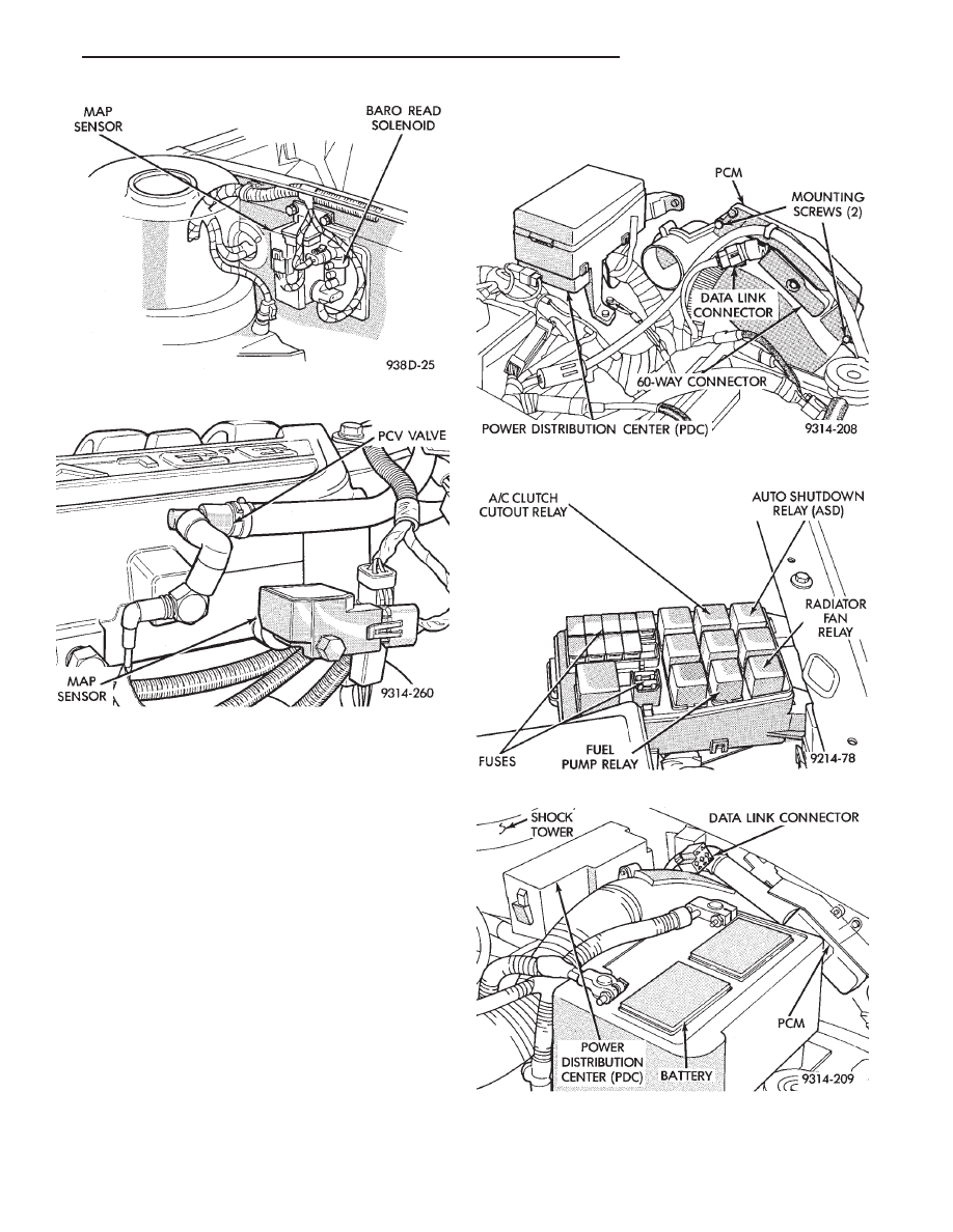
On AC, AG, AJ and AY models, the ASD relay and

fuel pump relay are located in the power distribution
center (Fig. 35, 36, 37, or 38).

On AA and AP models, the ASD relay and fuel

pump relay are mounted on the drivers side fender
well, next to the strut tower (Fig. 39).

Fig. 33 MAP Sensor—Turbo III Engine

Fig. 34 Map Sensor—3.3L and 3.8L Engines

Fig. 35 Power Distribution Center (PDC) (AC Body)

Fig. 36 Relay Identification (AC Body)

Fig. 37 Power Distribution Center (PDC)

(AG and AJ Body)

Ä

IGNITION SYSTEMS

8D - 33

Fig. 39 Relay Identification (AA and AP Bodies)

Fig. 38 Relay Identification (AG and AJ Body)

8D - 34

IGNITION SYSTEMS

Ä

2.2L TURBO III, 3.3L AND 3.8L IGNITION SYSTEM—DIAGNOSTIC PROCEDURES

INDEX

page

page

Check Coil Test—3.3L and 3.8L Engines

. . . . . . 36

Check Coil Test—Turbo III Engine

. . . . . . . . . . . 35

Coolant Temperature Sensor Test

. . . . . . . . . . . . 38

Crankshaft Position Sensor and Camshaft Position

Sensor Tests

. . . . . . . . . . . . . . . . . . . . . . . . . . 38

Failure to Start Test

. . . . . . . . . . . . . . . . . . . . . . 37

Failure to Start Test—Turbo III Engine

. . . . . . . . 36

Manifold Absolute Pressure (MAP) Sensor Test

38

Testing for Spark at Coil—3.3L and 3.8L Engines . 36
Testing for Spark at Coil—Turbo III Engine

. . . . . 35

TESTING FOR SPARK AT COIL—TURBO III ENGINE

WARNING: THE DIRECT IGNITION SYSTEM GENER-
ATES APPROXIMATELY 40,000 VOLTS. PERSONAL
INJURY COULD RESULT FROM CONTACT WITH
THIS SYSTEM.

The coil pack contains 2 independent coils. Each

coil must be checked individually.

CAUTION: Spark plug wire damage may occur if the
spark plug is moved more than 1/4 inch away from
the engine ground.

Remove the cable from number 1 spark plug. Insert

a clean spark plug into the spark plug boot, and
ground plug to the engine (Fig. 1).

CAUTION: Spark plug wire damage may occur if the
spark plug is moved more than 1/4 inch away from
the engine ground.

Crank the engine and look for spark across the

electrodes of the spark plug. Repeat the above test
for the remaining cylinders. If there is no spark dur-
ing the cylinder tests, proceed to the failure to start
test.

If one or more cylinders have irregular, weak, or

no spark, proceed to Check Coil Test.

CHECK COIL TEST—TURBO III ENGINE

Cylinders 1 & 4, and 2 & 3 are grouped together.
(1) Remove the ignition cables and measure the

resistance of the cables. Resistance must be between
3,000 to 12,000 ohms per foot of cable. Replace any
cable not within tolerance.

(2) Disconnect the electrical connector from the coil

pack (Fig. 2).

(3) Measure the primary resistance of each coil. At

the coil, connect an ohmmeter between the B+ pin and
the pin corresponding to the cylinders in question (Fig.
3). Resistance on the primary side of each coil should be
0.5-0.7 ohm. Replace the coil if resistance is not within
tolerance.

(4) Remove ignition cables from the secondary tow-

ers of the coil. Measure the secondary resistance of the
coil between the towers of each individual coil

Fig. 1 Testing For Spark

Fig. 2 Ignition Coil Electrical Connection—Turbo III

Engine

Fig. 3 Ignition Coil Terminal Identification

Ä

IGNITION SYSTEMS

8D - 35

(Fig. 4). Secondary resistance should be 11,600 to
15,800 ohms. Replace the coil if resistance is not
within tolerance.

FAILURE TO START TEST—TURBO III ENGINE

(1) Determine that sufficient battery voltage (12.4

volts nominal) is present for the cranking and igni-
tion systems.

(2) Connect a voltmeter to the wiring harness coil

connector at the B+ pin (Fig. 5).

(3) Crank the engine for 5 seconds while monitor-

ing the voltage at the B+ connector terminal. If the
voltage remains near zero during the entire period of
cranking, check the auto shutdown relay and PCM.
Refer to DRBII scan tool and the appropriate Power-
train Diagnostic Procedures manual. Refer to Group
14 for description of On Board Diagnostics.

(4) If voltage is at near-battery voltage, and drops

to zero after 1-2 seconds of cranking, check the cam-
shaft position sensor and crankshaft position sensor
and their circuits. Refer to the DRBII scan tool and
the appropriate Powertrain Diagnostic Procedure
manual. Refer to Group 14 for a description of On-
Board Diagnostics.

(5) If voltage remains at near-battery voltage dur-

ing the entire 5 seconds, turn the key off, remove the

PCM 60-way connector. Check the 60-way for any
terminals loose from the connector (push-out).

TESTING FOR SPARK AT COIL—3.3L AND 3.8L
ENGINES

WARNING: THE ENGINE DIRECT IGNITION SYSTEM
GENERATES APPROXIMATELY 40,000 VOLTS. PER-
SONAL INJURY COULD RESULT FROM CONTACT
WITH THIS SYSTEM.

The coil pack contains 3 independent coils. Each coil

must be checked individually.

CAUTION: Spark plug wire damage may occur if the
spark plug is moved more than 1/4 inch away from the
engine ground.

Remove the cable from number 2 spark plug. Insert a

clean spark plug into the spark plug boot, and ground
plug to the engine (Fig. 1).

Crank the engine and look for spark across the

electrodes of the spark plug. Repeat the above test for
the five remaining cylinders. If there is no spark
during all cylinder tests, proceed to the failure to start
test.

If one or more tests indicate irregular, weak, or no

spark, proceed to Check Coil Test.

WARNING: THE DIRECT IGNITION SYSTEM GENER-
ATES APPROXIMATELY 40,000 VOLTS. PERSONAL
INJURY COULD RESULT FROM CONTACT WITH THIS
SYSTEM.

CHECK COIL TEST—3.3L AND 3.8L ENGINES

Coil one fires cylinders 1 and 4, coil two fires

cylinders 2 and 5, coil three fires cylinders three
and six.

Each coil tower is labeled with the number of the

corresponding cylinder.

(1) Remove the ignition cables and measure the

resistance of the cables. Resistance must be between
3,000 to 12,000 ohms per foot of cable. Replace any
cable not within tolerance.

(2) Disconnect the electrical connector from the coil

pack (Fig. 6).

(3) Measure the primary resistance of each coil. At

the coil, connect an ohmmeter between the B+ pin and
the pin corresponding to the cylinders in question (Fig.
7). Resistance on the primary side of each coil should be
0.5 - 0.7 ohm. Replace the coil if resistance is not within
tolerance.

(4) Remove ignition cables from the secondary tow-

ers of the coil. Measure the secondary resistance of the
coil between the towers of each individual coil (Fig. 8).
Refer to the Coil Specifications Chart in the Specifica-
tions section of this group. Replace the coil if resistance
is not within tolerance.

Fig. 4 Checking Ignition Coil Secondary

Resistance—Turbo III Engines

Fig. 5 Wiring Harness Coil Connector—Turbo III

Engine

8D - 36

IGNITION SYSTEMS

Ä


Content   ..  291  292  293  294   ..