Chrysler Le Baron, Dodge Dynasty, Plymouth Acclaim. Manual - part 287


  Index      Chrysler     Chrysler Le Baron, Dodge Dynasty, Plymouth Acclaim - service repair manual 1993 year


Search            


Content   ..  285  286  287  288   ..


Chrysler Le Baron, Dodge Dynasty, Plymouth Acclaim. Manual - part 287


nal. From the pick-up signal, the PCM determines
engine speed and ignition timing (coil dwell). If the
PCM does not receive a distributor signal when the
ignition switch is in the Run position, it will de-en-
ergize both relays. When the relays are de-energized,
battery voltage is not supplied to the fuel injector, ig-
nition coil, fuel pump and oxygen sensor heating el-
ement.

On AC, AG, AJ and AY models, the ASD relay and

fuel pump relay are located in the power distribution
center (Fig. 24, 25, 26, or 27).

On AA and AP models, the ASD relay and fuel

pump relay are mounted on the drivers side fender
well, next to the strut tower (Fig. 28).

IGNITION COIL

The 2.2L TBI, 2.5L TBI, 2.5L MPI and 3.0L en-

gines use an epoxy type coil. The coils are not oil
filled. The windings are embedded in a heat and vi-
bration resistant epoxy compound.

The powertrain control module (PCM) operates the

ignition coil through the auto shutdown (ASD) relay.

When the relay is energized by the PCM, battery
voltage is connected to the ignition coil positive ter-
minal. The PCM will de-energize the ASD relay if it
does not receive an input from the distributor pick-

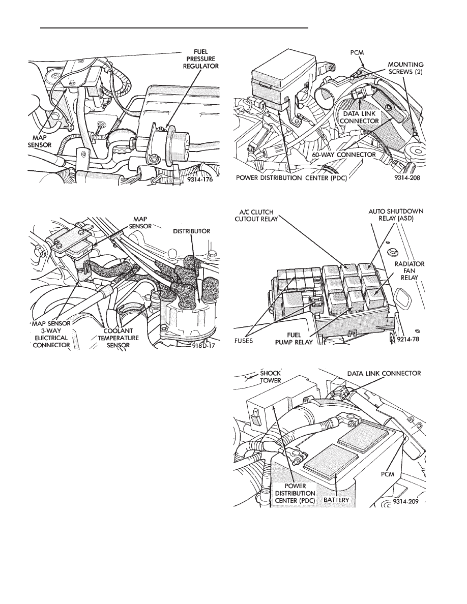
Fig. 22 MAP Sensor—2.5L MPI (Flexible Fuel

AA-Body) Engines

Fig. 23 MAP Sensor—3.0L Engine

Fig. 24 Power Distribution Center (PDC) (AC Body)

Fig. 25 Relay Identification (AC Body)

Fig. 26 Power Distribution Center (PDC) (AG and AJ

Body)

Ä

IGNITION SYSTEMS

8D - 9

up. Refer to Auto Shutdown (ASD) Relay and Fuel
Pump Relay in this section.

On 2.2L TBI, 2.5L TBI and 2.5L MPI engines, the

ignition coil is mounted to the thermostat housing
(Fig. 29). On 3.0L engines the coil is mounted on the
rear of the intake manifold next to the air cleaner
(Fig. 30).

Fig. 28 Relay Identification (AA and AP Bodies)

Fig. 29 Ignition Coil—2.2L TBI, 2.5L TBI and 2.5L

MPI Engines

Fig. 30 Ignition Coil—3.0L Engine

Fig. 27 Relay Identification (AG and AJ Body)

8D - 10

IGNITION SYSTEMS

Ä

2.2L TBI, 2.5L TBI, 2.5L MPI AND 3.0L IGNITION SYSTEMS—DIAGNOSTIC

PROCEDURES

INDEX

page

page

Coolant Temperature Sensor Test

. . . . . . . . . . . . 13

Failure to Start Test—2.5L TBI and 3.0L Engines

12

General Information

. . . . . . . . . . . . . . . . . . . . . . . 11

Ignition Coil

. . . . . . . . . . . . . . . . . . . . . . . . . . . . . 11

Manifold Absolute Pressure (MAP) Sensor Test

13

Poor Performance Test

. . . . . . . . . . . . . . . . . . . . 13

Spark Plugs

. . . . . . . . . . . . . . . . . . . . . . . . . . . . 11

Testing for Spark at Coil

. . . . . . . . . . . . . . . . . . . 11

GENERAL INFORMATION

For additional information, refer to On Board Di-

agnostics in the Fuel Injection General Diagnosis
sections of Group 14. Also, refer to the DRBII scan
tool and appropriate Powertrain Diagnostic Proce-
dures Manual.

SPARK PLUGS

Faulty or fouled spark plugs may perform well at

idle speed, but frequently fail at higher engine
speeds. Faulty plugs can be identified in a number of
ways: poor fuel economy, power loss, decrease in en-
gine speed, hard starting and, in general, poor en-
gine performance.

Spark plugs also malfunction because of carbon

fouling, excessive electrode air gap, or a broken insu-
lator. Refer to the General Information Section of
this group for spark plug diagnosis.

IGNITION COIL

The ignition coil is designed to operate without an

external ballast resistor.

Inspect the coil for arcing. Test the coil according

to coil tester manufacturer’s instructions. Test coil
primary and secondary resistance. Replace any coil
that does not meet specifications. Refer to the Coil
Resistance chart.

If the ignition coil is replaced due to a burned

tower, carbon tracking, arcing at the tower, or dam-
age to the terminal or boot on the coil end of the sec-
ondary cable, the cable must be replaced. Arcing at

the tower will carbonize the nipple which, if it is con-
nected to a new coil, will cause the coil to fail.

If a secondary cable shows any signs of damage,

the cable should be replaced with a new cable and
new terminal. Carbon tracking on the old cable can
cause arcing and the failure of a new coil.

TESTING FOR SPARK AT COIL

WARNING:

APPLY

PARKING

BRAKE

AND/OR

BLOCK THE WHEELS BEFORE PERFORMING ANY
TEST WITH THE ENGINE RUNNING.

CAUTION: Spark plug cables may be damaged if
this test is performed with more than 1/4 inch clear-
ance between the cable and engine ground.

Remove the coil secondary cable from the distribu-

tor cap. Hold the end of cable about 6 mm (1/4-inch)
away from a good engine ground (Fig. 1). Crank the
engine and inspect for spark at the coil secondary ca-
ble.

There must be a constant spark at the coil second-

ary cable. If the spark is constant, have a helper con-
tinue to crank engine and, while slowly moving coil
secondary cable away from ground, look for arcing at
the coil tower. If arcing occurs at the tower, replace
the coil. If spark is not constant or there is no spark,
proceed to the failure to start test.

If a constant spark is present and no arcing occurs

at the coil tower, the ignition system is producing
the necessary high secondary voltage. However,

COIL RESISTANCE

Ä

IGNITION SYSTEMS

8D - 11

make sure that the spark plugs are firing. Inspect the
distributor rotor, cap, spark plug cables, and spark
plugs. If they are in proper working order, the ignition
system is not the reason why the engine will not start.
Inspect the fuel system and engine for proper opera-
tion.

FAILURE TO START TEST—2.5L TBI AND 3.0L
ENGINES

Before proceeding with this test make sure

Testing For Spark At Coil has been performed.
Failure to do this may lead to unnecessary diag-
nostic time and wrong test results.

WARNING: BE SURE TO APPLY PARKING BRAKE
AND/OR BLOCK WHEELS BEFORE PERFORMING
ANY TEST WITH THE ENGINE RUNNING.

(1) Battery voltage must be at least 12.4 volts to

perform test.

(2) Crank the engine for 5 seconds while monitoring

the voltage at the coil positive (+) terminal (Fig. 2 or
Fig. 3). If the voltage remains near zero during the
entire period of cranking, refer to Group 14 for On-
Board Diagnostic checks. Also, refer to the DRBII scan
tool and the appropriate Powertrain Diagnostic Proce-
dures manual. These checks will help diagnose prob-
lems with the PCM and auto shutdown relay.

(3) If voltage is at near-battery voltage and drops to

zero after 1-2 seconds of cranking, refer to On-Board
Diagnostic in Group 14. Also, refer to the DRBII scan
tool and the appropriate Powertrain Diagnostic Proce-
dures manual. These tests will help check the distribu-
tor reference pickup circuit to the PCM.

(4) If voltage remains at near battery voltage during

the entire 5 seconds, with the key off, remove the
PCM 60-way connector. Check the 60-way connector
for any terminals that are pushed out or loose.

(5) Remove the connector to coil (+) and connect a

jumper wire between battery (+) and coil (+).

(6) Using the special jumper (Fig. 4), momentarily

ground terminal #19 of the 60-way connector (Fig.
5). A spark should be generated when the ground is
removed.

(7) If spark is generated, replace the PCM.
(8) If no spark is seen, use the special jumper to

ground the coil (-) terminal directly.

(9) If spark is produced, inspect wiring harness for

an open condition.

Fig. 2 Coil Terminals—2.2L TBI, 2.5L TBI and 2.5L

MPI Engines

Fig. 3 Coil Terminals—3.0L Engine

Fig. 4 Special Jumper to Ground Coil Negative

Fig. 1 Checking for Spark

8D - 12

IGNITION SYSTEMS

Ä


Content   ..  285  286  287  288   ..