Chrysler Le Baron, Dodge Dynasty, Plymouth Acclaim. Manual - part 285
IGNITION SYSTEMS
CONTENTS
page
page
2.2L TBI, 2.5L TBI, 2.5L MPI AND 3.0L IGNITION
SYSTEMS—DIAGNOSTIC PROCEDURES
. . . . . 11
2.2L TBI, 2.5L TBI, 2.5L MPI AND 3.0L IGNI-
TION SYSTEMS—SERVICE PROCEDURES
. 14
2.2L TBI, 2.5L TBI, 2.5L MPI AND 3.0L IGNI-
TION SYSTEMS—SYSTEM OPERATION
. . . . 1
2.2L TURBO III, 3.3L AND 3.8L IGNITION
SYSTEM—DIAGNOSTIC PROCEDURES
. . . . 35
2.2L TURBO III, 3.3L AND 3.8L IGNITION
SYSTEM—SYSTEM OPERATION
. . . . . . . . . 24
2.2L TURBO III, 3.3L AND 3.8L IGNITION
SYSTEMS—SERVICE PROCEDURES
. . . . . . 39
IGNITION SWITCH
. . . . . . . . . . . . . . . . . . . . . . 45
SPECIFICATIONS
. . . . . . . . . . . . . . . . . . . . . . . 47
GENERAL INFORMATION
Throughout this group, references are made to par-
ticular vehicles by letter designation. A chart ex-
plaining the designations appears in the Introduction
Section of this manual.
2.2L TBI, 2.5L TBI, 2.5L MPI AND 3.0L IGNITION SYSTEMS—SYSTEM
OPERATION
INDEX
page
page
Auto Shutdown (ASD) Relay and Fuel Pump Relay . 8
Coolant Temperature Sensor
. . . . . . . . . . . . . . . . . 7
Distributor Cap
. . . . . . . . . . . . . . . . . . . . . . . . . . . 1
Distributor Pick-Up—3.0L Engine
. . . . . . . . . . . . . . 7
Distributor Pick-Up—PCM Input
. . . . . . . . . . . . . . . 6
General Information
. . . . . . . . . . . . . . . . . . . . . . . . 1
Ignition Coil
. . . . . . . . . . . . . . . . . . . . . . . . . . . . . . 9
Manifold Absolute Pressure (MAP) Sensor
. . . . . . 8
Powertrain Control Module (PCM)
. . . . . . . . . . . . . 6
Rotor
. . . . . . . . . . . . . . . . . . . . . . . . . . . . . . . . . . 2
Spark Plug Cables
. . . . . . . . . . . . . . . . . . . . . . . . 2
Spark Plugs
. . . . . . . . . . . . . . . . . . . . . . . . . . . . . 3
GENERAL INFORMATION
This section describes the ignition systems of the
2.2L TBI, 2.5L TBI, 2.5L MPI (flexible fuel AA-body)
and 3.0L engines.
The Fuel Injection sections of Group 14 explain On
Board Diagnostics.
Group 0, Lubrication and Maintenance, contains
general maintenance information for ignition related
items. The Owner’s Manual also contains mainte-
nance information.
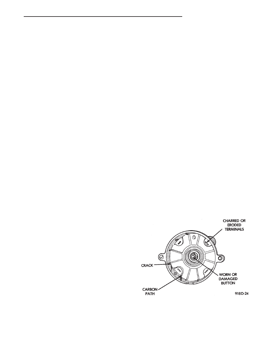
DISTRIBUTOR CAP
Remove the distributor cap and inspect the inside
for flash over, cracking of carbon button, lack of
spring tension on carbon button, cracking of cap, and
burned, worn terminals (Fig. 1). Also check for bro-
ken distributor cap towers. If any of these conditions
are present the distributor cap and/or cables should
be replaced.
When replacing the distributor cap, transfer cables
from the original cap to the new cap one at a time.
Ensure each cable is installed into the corresponding
tower of the new cap. Fully seat the wires into the
towers. If necessary, refer to the appropriate engine
firing order diagram (Fig. 2 or Fig. 3).
Fig. 1 Distributor Cap Inspection
Ä
IGNITION SYSTEMS
8D - 1