Chrysler Le Baron, Dodge Dynasty, Plymouth Acclaim. Manual - part 283


  Index      Chrysler     Chrysler Le Baron, Dodge Dynasty, Plymouth Acclaim - service repair manual 1993 year


Search            


Content   ..  281  282  283  284   ..


Chrysler Le Baron, Dodge Dynasty, Plymouth Acclaim. Manual - part 283


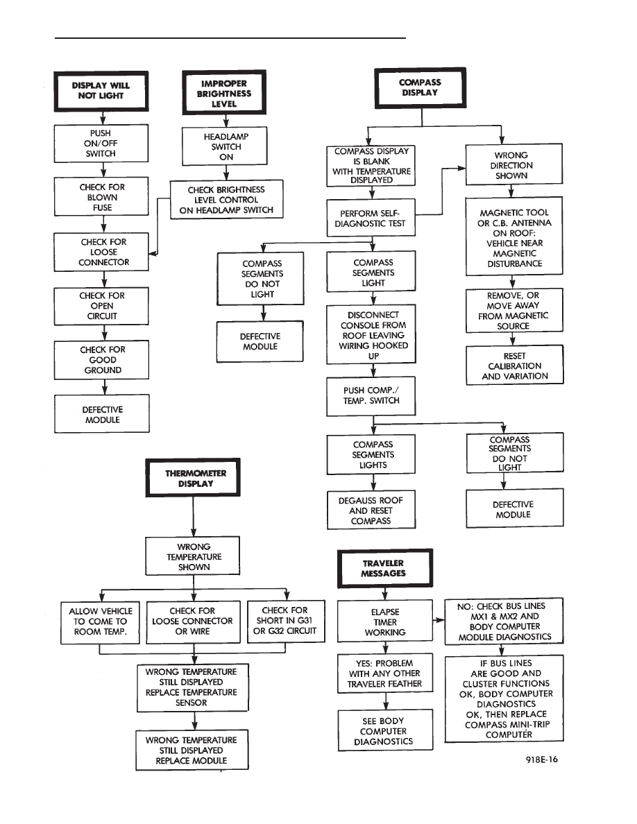
Fig. 7 Compass and Thermometer Diagnosis

Ä

OVERHEAD CONSOLE

8C - 19

OVERHEAD CONSOLE REPLACEMENT

(1) Unscrew the mounting screw in sun glass bin

compartment (Fig. 8).

(2) Slide console forward toward windshield until

the console unhooks from roof bracket.

(3) Disconnect wire harness from console.
(4) For installation reverse above procedures.

COMPASS MODULE REPLACEMENT

(1) Remove overhead console.
(2) Using a small screwdriver, release the 2 snaps

at rear of compass module (Fig. 9).

(3) After releasing the 2 snaps, slide compass mod-

ule rearward until free of mounting bar.

(4) For installation reverse above procedures.

ELECTRONIC VEHICLE INFORMATION CENTER
(EVIC) REMOVAL

(1) Use a straight edge tool to pry out one end of

the EVIC center and continue to disengage six clips
along the length of the message center.

(2) Remove the EVIC center and disconnect the

wiring.

(3) For installation reverse the above procedures.

AMBIENT TEMPERATURE SENSOR REMOVAL

(1) Raise and support vehicle on safety stands.
(2) From behind front bumper fascia, remove screw

attaching sensor to radiator closure panel (Fig. 10).

(3) For installation, reverse above procedures.

ENGINE NODE SENSOR REMOVAL

(1) Raise and support vehicle on safety stands.
(2) From behind front bumper fascia, remove

screws attaching engine node to bumper fascia (Fig.
11).

(3) For installation, reverse above procedures.

Fig. 8 Overhead Console Mounting

Fig. 9 Compass Module Removal

Fig. 10 Ambient Temperature Sensor

Fig. 11 Engine Node

8C - 20

OVERHEAD CONSOLE

Ä

AP BODY

INDEX

page

page

Ambient Temperature Sensor Removal

. . . . . . . . 25

Compass Calibration

. . . . . . . . . . . . . . . . . . . . . . 21

Compass Diagnostics

. . . . . . . . . . . . . . . . . . . . . 23

Compass Module Replacement

. . . . . . . . . . . . . . 25

Demagnetizing Procedure

. . . . . . . . . . . . . . . . . . 22

Map Reading Lamps Operation

. . . . . . . . . . . . . . 21

Overhead Console Replacement

. . . . . . . . . . . . . 25

Thermometer and Compass

. . . . . . . . . . . . . . . . 21

Variance Procedure

. . . . . . . . . . . . . . . . . . . . . . . 22

MAP READING LAMPS OPERATION

The map lamps are actuated by pressing on the

lens (Fig. 1).

LAMP REPLACEMENT

(1) Remove lens by inserting a screw driver or

knife blade into slot located along-side of lens. Once
screwdriver is inserted pry lens to the side and swing
down as it unhooks from housing edge.

(2) Remove lamp by pulling straight down.
(3) Install new lamp by pushing firmly into recep-

tacle.

(4) Snap lens into position taking care to orient

the tabs on the lens with the slots in the housing.

MAP LAMP TEST

(1) Press each lamp switch. Right hand switch

should light passenger lamp and left hand switch
should light drivers lamp.

(2) If lamp does not illuminate check for a burned

out lamp, voltage, defective switch or faulty wiring.

THERMOMETER AND COMPASS

The ignition switch must be in the ON or ACCES-

SORY position before the temperature and compass
reading can be displayed. The Comp/Temp switch
turns the compass display on and off. The US/Metric
switch changes the temperature reading from Fahr-
enheit to Celsius (Fig. 2).

When the vehicle is standing still, engine compart-

ment temperatures may be radiated to the tempera-
ture sensor. Therefore the most accurate ambient
temperature readings are displayed when the vehicle
is moving in a forward motion.

When the ignition switch is in the ON position the

temperature display is updated every 5 minutes.
When the ignition switch is turned off the last dis-
played temperature reading stays in memory. When
the ignition switch is turned on again the thermom-
eter will display the memory temperature for 1
minute; then update the display to the actual tem-
perature within 5 minutes.

COMPASS CALIBRATION

Do not attempt to set the compass near large metal

objects, such as, other vehicles, large buildings, or
bridges.

The compass unit automatically calibrates itself as

the vehicle is driven; therefore, no calibration should
be required. When the compass is first powered up,
the CAL light on the display should be on. The CAL
light will go off and the compass will be accurate af-
ter the vehicle completes one to three complete cir-
cles.

If the vehicle’s compass headings are inaccurate,

the compass also can be manually calibrated using
the following procedures:

(1) Depress and hold down both the Comp/Temp

button and the U.S./Metric button.

(2) The display will go off and after 5 seconds the

VAR light will come on. Continue to hold both but-
tons down.

(3) In approximately 10 seconds, the CAL light

will come on. Release both buttons and the display
will show the heading and outside temperature.

(4) Drive the vehicle 1 to 3 complete circles, with-

out turning ignition OFF. The CAL light will then
go off, showing the compass is calibrated.

Fig. 1 Overhead Console Lamp Replacement

Ä

OVERHEAD CONSOLE

8C - 21

(5) The variation may need to be adjusted. The

variation is the difference between magnetic north
and true north. To set variation refer the to Varia-
tion Setting Procedure.

If the compass portion of the display is not lit or

compass readings are not accurate after calibration.
The vehicle may have too much magnetism for the
compass to be accurate or the compass circuitry is
not working properly. Refer to Variance Procedure,
Demagnetizing Procedure and/or Compass Diagnos-
tics.

VARIANCE PROCEDURE

Variance is the difference between magnetic North

and geographic North. In some areas the difference
between magnetic and geographic North is great
enough to cause the compass to give false readings. If
this occurs, the variance must be set.

VARIANCE SETTING PROCEDURE

To set the variance, depress and hold down both

the Comp/Temp button and the U.S./Metric button.
The display will go off and after 5 seconds the VAR
light will come on. Release both buttons. Using the
zone map (Fig. 3) to find your geographic location,
note the zone which you are in. Press the U.S./Metric

button until the zone number appears on the display.
Press the Comp/Temp button to enter your zone
number.

Do not attach magnetic devices, such as magnetic

CB antennas to the vehicle roof, as they can cause
the compass to give false readings.

DEMAGNETIZING PROCEDURE

Every vehicle has its own magnetic field. This

magnetic field is created by the various processes a
steel roof goes through when the vehicle is built. A
magnetic field also can be created if the roof is sub-
jected to a magnet, example:
• Magnetic c.b. antenna

• Magnetic tipped screwdriver, etc.

If the roof becomes magnetized use a demagnetiz-

ing tool 6029 to demagnetize the roof.

In this demagnetizing procedure you will use the

demagnetizing tool to demagnetize the roof and
mounting screws in the overhead console. It is impor-
tant that you follow the instructions below exactly.
The mounting screws and the mounting brackets
around the compass area are steel, and therefore aid
in the demagnetizing of the roof panel.

(1) Be sure the ignition switch is in the OFF posi-

tion before you begin the demagnetize procedure.

(2) Open the sun glass compartment to gain access

to the overhead console mounting screws.

Fig. 2 Overhead Console

8C - 22

OVERHEAD CONSOLE

Ä


Content   ..  281  282  283  284   ..