Chrysler Le Baron, Dodge Dynasty, Plymouth Acclaim. Manual - part 282


  Index      Chrysler     Chrysler Le Baron, Dodge Dynasty, Plymouth Acclaim - service repair manual 1993 year


Search            


Content   ..  280  281  282  283   ..


Chrysler Le Baron, Dodge Dynasty, Plymouth Acclaim. Manual - part 282


VISUAL MESSAGES

Following are the visual messages and the condi-

tions under which, the messages will be given:
• Keys in ignition

• Exterior lamps on

These messages will appear if the conditions are

present and the driver’s door is open while the igni-
tion switch is in the OFF, LOCK, or ACC positions.
A tone will sound until the condition is corrected or
the door is closed.
• Passenger door ajar

• Driver door ajar

• Trunk ajar

• Park brake engaged

• Right rear door ajar

• Left rear door ajar

These messages will appear if a condition is de-

tected after the vehicle is in motion. When the con-
dition is corrected, a short tone will sound to
acknowledge the action.

LOW OIL PRESSURE
If this message is displayed while the vehicle is at

cruising speeds, immediate attention is required. If
this message appears at idle speed, increase the idle
speed and the message should go off. If the message
remains on, immediate attention is required.

ENGINE TEMP CRITICAL
This message appears when a sensor has deter-

mined that the engine coolant is overheating. If this
message comes on and stays on, immediate action is
required.

COOLANT LEVEL LOW
LOW FUEL LEVEL
LOW BRAKE FLUID

WASHER FLUID LOW
These messages will appear if a continuous warn-

ing condition is detected while the engine is running.
Inspection is required. To clear this message from
the display, after the condition is corrected, the igni-
tion switch must be turned OFF.

CHECK TRANS
This message will appear if a continuous warning

condition is detected while the engine is running. Im-
mediate attention is recommended. To clear this mes-
sage from the display, after the condition has been
corrected, the ignition switch must be turned OFF.

VOLTAGE IMPROPER
This message will appear if a continuous warning

condition is detected. Immediate attention is re-
quired. To clear this message from the display, after
the condition has been corrected, the ignition switch
must be turned OFF.

TURN SIGNAL ON
This message will appear if the turn signal is left

on while vehicle speed is over 15 mph and the vehi-
cle has traveled over one-half mile.

FASTEN SEAT BELTS
An intermittent chime tone will sound for several

seconds if the seat belt is not fastened.

CHK ENGINE OIL LEVEL
If this message is delivered, a check of the engine

oil dipstick is suggested. To clear this message, after
the condition is corrected, the ignition switch must
be turned OFF.

HEADLAMP OUT
BRAKE LAMP OUT
TAIL LAMP OUT
These conditions are monitored only when the

lamps are on. The message will remain, even after
the lamp is replaced, until the lamp is turned on and
operates.

SERVICE REMINDER
The

maintenance

reminder

statement

is

pro-

grammed to provide general information only. Refer
to Group 0, Lubrication & Maintenance for specific
vehicle requirements.

The service reminder message is displayed at 7,500

miles or 12 months intervals, which ever comes first.

MONITORED SYSTEMS OK
If there is no warning condition to report, the mes-

sage Monitored Systems OK is displayed (Fig. 3).

ENGINE COMPARTMENT NODE (ECN)

The Engine Compartment Node is a microcomputer

controlled unit which, informs the Electronic Vehicle
Information Center (EVIC) via the CCD bus of:
• Outside temperature

• Compass direction

and the following warning messages:

• Low Brake Fluid

• Low Coolant Level

• Low Engine Oil Level

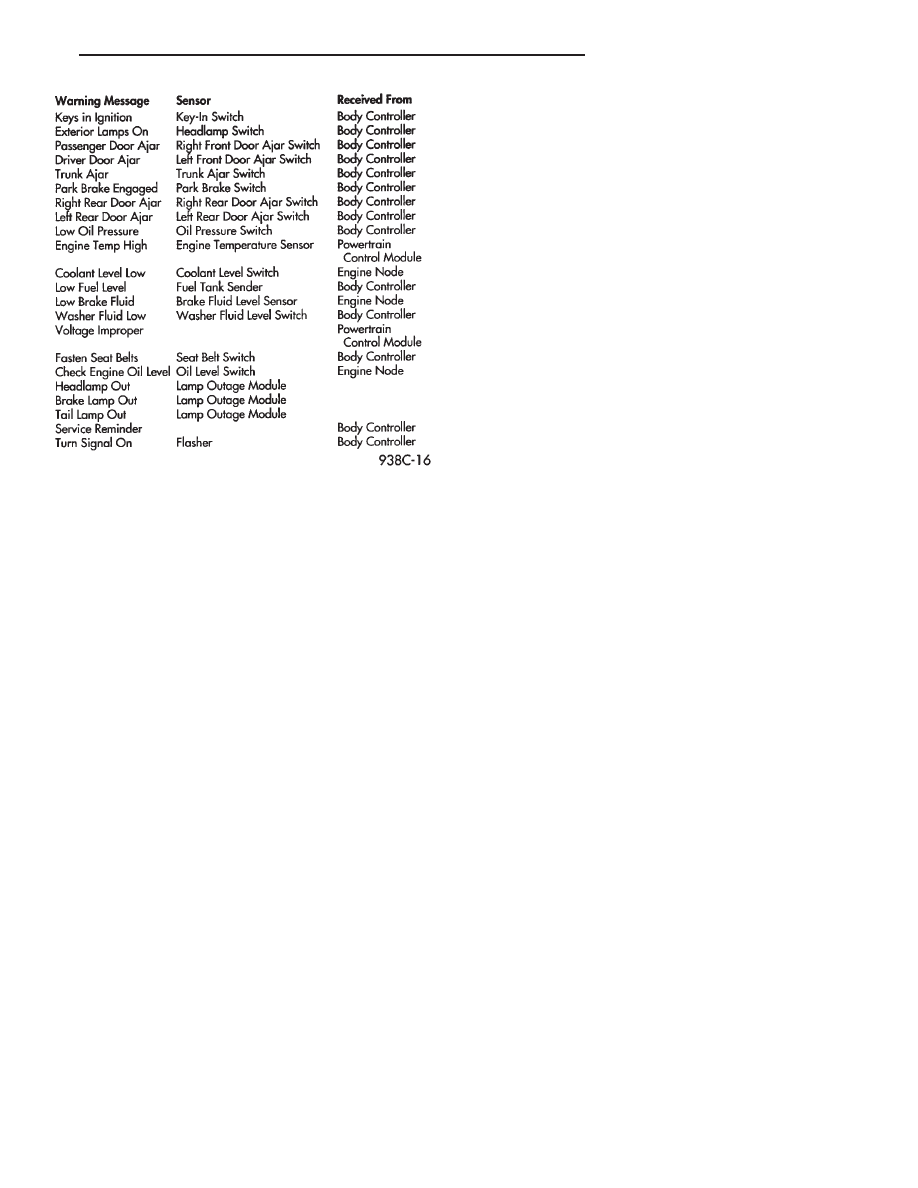
Fig. 3 EVIC Messages and Sensors

Ä

OVERHEAD CONSOLE

8C - 15

The Engine Compartment Node is located behind

the grille.

For complete diagnostic procedures for the Engine

Compartment Node, refer to the Body Diagnostic
Test Procedure Manual.

ENGINE COMPARTMENT NODE COMPASS
CALIBRATION

Automatic or Manual Calibration, refer to AY

Body Compass Calibration.

THERMOMETER AND COMPASS

OPERATION

The ignition switch must be in the ON or ACCES-

SORY position before the temperature and compass
reading can be displayed. The Comp/Temp switch
turns the compass display on and off. The US/Metric
switch changes the temperature reading from Fahr-
enheit to Celsius (Fig. 4).

When the vehicle is standing still, engine compart-

ment temperatures may be radiated to the tempera-
ture sensor. Therefore the most accurate ambient
temperature readings are displayed when the vehicle
is moving in a forward motion.

When the ignition switch is in the ON position the

temperature display is updated every 5 minutes.
When the ignition switch is turned off the last dis-
played temperature reading stays in memory. When

the ignition switch is turned on again the thermom-
eter will display the memory temperature for 1
minute; then update the display to the actual tem-
perature within 5 minutes.

COMPASS CALIBRATION

Do not attempt to set the compass near large metal

objects, such as, other vehicles, large buildings, or
bridges.

The compass unit automatically calibrates itself as

the vehicle is driven; therefore, no calibration should
be required. When the compass is first powered up,
the CAL light on the display should be on. The CAL
light will go off and the compass will be accurate af-
ter the vehicle completes 1 to 3 complete circles.

If the vehicle’s compass headings are inaccurate,

the compass also can be manually calibrated using
the following procedures:

(1) Depress and hold down both the Comp/Temp

button and the U.S./Metric button.

(2) The display will go off and after 5 seconds the

VAR light will come on. Continue to hold both but-
tons down.

(3) In approximately 10 seconds, the CAL light

will come on. Release both buttons and the display
will show the heading and outside temperature.

Fig. 4 Overhead Console

8C - 16

OVERHEAD CONSOLE

Ä

(4) Drive the vehicle 1 to 3 complete circles. The

CAL light will then go off, showing the compass is
calibrated.

If the compass portion of the display:

• It does not display.

• Readings are not accurate after calibration.

• The vehicle may have too much magnetism for the
compass to be accurate.
• The compass circuitry is not working properly.

• Refer to Variance Procedure, Demagnetizing Pro-
cedure and/or Compass Diagnostics.

VARIANCE PROCEDURE

Variance is the difference between magnetic North

and geographic North. In some areas the difference
between magnetic and geographic North is great
enough to cause the compass to give false readings. If
this occurs, the variance must be set.

To set the variance, depress and hold down both

the Comp/Temp button and the U.S./Metric button.
The display will go off and after 5 seconds the VAR
light will come on. Release both buttons. Using the
zone map (Fig. 5) to find your geographic location,
note the zone which, you are in. Press the U.S./Met-
ric button until the zone number appears on the dis-
play. Press the Comp/Temp button to enter your zone
number.

Do not attach magnetic devices, such as magnetic

CB antennas to the vehicle roof, as they can cause
the compass to give false readings.

DEMAGNETIZING PROCEDURE

Every vehicle has its own magnetic field. This

magnetic field is created by the various processes a
steel roof goes through when the vehicle is built. A
magnetic field also can be created if the roof is sub-
jected to a magnet, example:
• Magnetic c.b. antenna

• Magnetic tipped screwdriver and etc.

If the roof becomes magnetized use a demagnetizer

tool 6029 to demagnetize the roof.

In this demagnetizing procedure you will use the

demagnetizing tool to demagnetize the roof and
mounting screws in the overhead console. It is impor-
tant that you follow the instructions below exactly.
The mounting screws and the mounting brackets
around the compass area are steel, and therefore aid
in the demagnetizing of the roof panel.

(1) Be sure the ignition switch is in the OFF posi-

tion before you begin the demagnetize procedure.

(2) Open the sun glass compartment to gain access

to the overhead console mounting screws.

(3) Plug the demagnetizing tool into a standard

110/115 volt AC outlet, keeping the demagnetizing
tool at least 12 inches away from the compass area
when plugging it in.

(4) Slowly approach the console mounting screw

with the plastic coated tip of the tool for at least 2
seconds.

(5) With the demagnetizing tool still energized,

slowly back it away from the screw until the tip is at
least 12 inches from the screw head.

(6) After you have pulled at least 12 inches from

the last screw, remove the demagnetizing tool from
inside of the vehicle and disconnect it from the elec-
trical outlet.

(7) Place an 8 1/2 X 11 inch piece of paper length-

wise on the roof of vehicle directly above compass.
The purpose of the paper is to protect the roof panel
from scratches and define the area to be demagne-
tized.

(8) Plug in the demagnetizing tool, keeping it at

least 2 feet away from the compass unit.

(9) Slowly approach the center of the roof panel at

the windshield with the demagnetizing tool plugged
in.

(10) Contact the roof panel with the tip of the tool.

Using slow sweeping motions of 1/2 inch between
sweeps. Move the tool approximately 4 inches either
side of the centerline and at least 11 inch back from
the windshield.

(11) With the demagnetizing tool still energized,

slowly back away from the roof panel until the tip is
at least 2 feet from the roof before unplugging the
tool.

Fig. 5 Variance Zone Map

Ä

OVERHEAD CONSOLE

8C - 17

(12) Recalibrate compass.

COMPASS DIAGNOSTICS

To place the unit into the diagnostics mode, turn

the vehicle ignition off. Depress the Comp/Temp but-
ton while turning on the ignition/run switch. The
display will then show DO. There are 3 tests that
can be performed when in the diagnostics mode.
Press the U.S./Metric button to choose test desired
(Fig. 6 and 7).

Test 1 (d1) determines the magnetic field strength

at the compass. The compass displays compensation
numbers which, correspond to the current magnetic
field strength at the compass. The letter N is dis-
played in the compass portion of the display. While a
number which, corresponds to the magnetic field
strength in the North/South direction is displayed.
The temperature portion of the display or the letter
W is displayed in the compass portion of the display.
A number which, corresponds to the magnetic field
strength in the East/West direction is displayed in
the temperature portion of the display. For proper
compass operation the numbers should be between 1
and 14. A number of 7 or 8 is ideal (no vehicle mag-
netism) while numbers approaching 1 or 14 show
that the vehicle is highly magnetic. If the numbers
show that the vehicle is highly magnetic, perform
the demagnetized procedure in this Group and retest
for magnetism at compass. If the compass is not re-
ceiving information from the CCD bus, F1 will be
displayed 15 seconds after this test is requested. Re-
fer to AG and AJ Body Diagnostic Procedure Manual
for further testing procedures.

Test 2 (d2) checks the electronic circuits of the

compass, temperature, and CCD bus. If the test
passes d2 will be displayed, and if the test fails F2
will be displayed. Refer to AG and AJ Body Diagnos-
tic Procedure Manual for further testing procedures.

Test 3 (d3) performs a walking segment test which,

sequentially puts different directions and numbers on
the display. If any segment fails, replace the compass
module.

Fig. 6 Terminal Identification

8C - 18

OVERHEAD CONSOLE

Ä


Content   ..  280  281  282  283   ..