Chrysler Le Baron, Dodge Dynasty, Plymouth Acclaim. Manual - part 280


  Index      Chrysler     Chrysler Le Baron, Dodge Dynasty, Plymouth Acclaim - service repair manual 1993 year


Search            


Content   ..  278  279  280  281   ..


Chrysler Le Baron, Dodge Dynasty, Plymouth Acclaim. Manual - part 280


• To set DAY of WEEK, press TIME button. An ar-
row will appear on the display and point to the Day.
Press and hold the SET button to move the day for-
ward or INFO button to move it backward.
• To set DAY of MONTH, press TIME button. The
arrow will point to Date. Press and hold the SET
button to advance the date or INFO button to move
it backwards.
• To set MONTH of YEAR, press TIME button. The
arrow will point to the Month. Press and hold the
SET button to advance the Month forward or INFO
button to move backward.

TEMP button, pressing the Temp button will dis-

play:
• The temperature outside the vehicle

• Vehicle direction define by an eight point compass

If Compass has lost calibration or not receiving

good information from the engine compartment node,
an asterisk (*) will flash on the display and the word
calibrate will appear. Refer to Compass Calibration.

FUEL BUTTON, WILL DISPLAY:

• Pressing FUEL button the first time will show, the
estimated number of miles that can be driven with
the remaining fuel. The destination to empty indica-
tion will vary every few seconds as the amount of
fuel and fuel efficiency is calculated. This function
can not be reset.
• Pressing the FUEL button second time; will dis-
play the fuel consumed.
• Pressing the FUEL button third time; will display
the average fuel economy in miles per gallon since last
reset. The display will be updated every 16 seconds.
• Pressing the FUEL button forth time, the current
fuel economy will be displayed. The current fuel
economy will be up updated every two seconds.
• To reset Fuel consumed, press SET button until
the fuel consumed message is displayed and then
within five seconds press SET button.
• To reset AVERAGE FUEL ECONOMY, press the
FUEL button until average fuel economy is displayed
and within five seconds press SET button.

TRIP RESET, press FUEL button and wait four

seconds press the SET button twice. This clears all
trip information and the message Trip Reset will be
displayed. This will occur only if a reset function is
currently being displayed. The reset functions:
• Fuel consumed

• Average fuel economy message

INFO button, will active a MONITORED SYS-

TEMS OK message on display if all monitored sys-
tems are operating properly. If a problem is detected,
the appropriate message will be displayed.

SET button, will clear the various functions after

they have been displayed. It is used to enter the
clock set or compass variance modes. This button is
also used to reset certain trip computer functions and
the maintenance reminder message.

The EVIC display may be turned off by pressing the

TIME and SET buttons at the same time. Pressing the
buttons a second time will restore the display.

EVIC INFORMATION SOURCES

The EVIC monitors information provided by the

body controller, engine compartment node and pow-
ertrain control module. Refer to Body Diagnostic Test
Procedure Manual for test procedures.

The Body Controller is a micro-controller unit

which, informs the EVIC overhead console via the
CCD bus of:
• Time of day

• Day of week

• Day of month

• Month of year

• Fuel range

• Fuel consumed

• Fuel efficiency

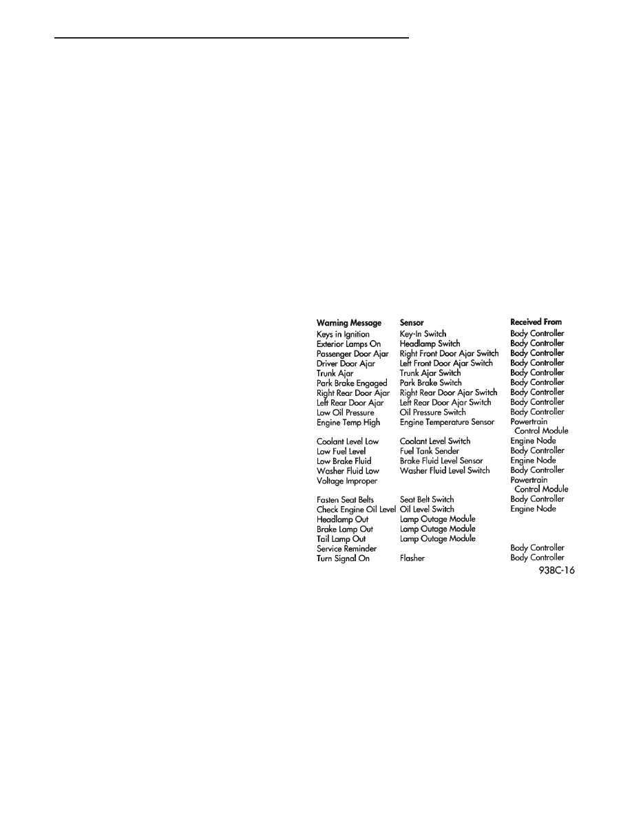
• Warning messages as noted in Fig. 2

The Engine Compartment Node is a microcomputer

controlled unit which, informs the EVIC overhead
console via the CCD bus of:
• Outside temperature

• Compass direction

THE FOLLOWING ARE WARNING MESSAGES:

• Low brake fluid

• Low coolant level

• Low engine oil level

The powertrain control module is a microcomputer

controlled unit which, informs the EVIC overhead con-
sole via the CCD bus of the following warning messages:
• Engine temperature high

• Voltage improper

Fig. 2 EVIC Messages and Sensors

Ä

OVERHEAD CONSOLE

8C - 7

VISUAL MESSAGES

Following are the visual messages and the condi-

tions under which, the messages will be given:
• Keys in ignition

• Exterior lamps on

These messages will appear if the conditions are

present and the driver’s door is open while the igni-
tion switch is in the OFF, LOCK, or ACC positions.
A tone will sound until the condition is corrected or
the door is closed.
• Passenger door ajar

• Driver door ajar

• Trunk ajar

• Park brake engaged

• Right rear door ajar

• Left rear door ajar

These messages will appear if a condition is de-

tected after the vehicle is in motion. When the con-
dition is corrected, a short tone will sound to
acknowledge the action.

LOW OIL PRESSURE
If this message is displayed while the vehicle is at

cruising speeds, immediate attention is required. If
this message appears at idle speed, increase the idle
speed and the message should go off. If the message
remains on, immediate attention is required.

ENGINE TEMP CRITICAL
This message appears when a sensor has determined

that the engine coolant is overheating. If this message
comes on and stays on, immediate action is required.

COOLANT LEVEL LOW
LOW FUEL LEVEL
LOW BRAKE FLUID
WASHER FLUID LOW
These messages will appear if a continuous warn-

ing condition is detected while the engine is running.
Inspection is required. To clear this message from
the display, after the condition is corrected, the igni-
tion switch must be turned OFF.

CHECK TRANS
This message will appear if a continuous warning

condition is detected while the engine is running. Im-
mediate attention is recommended. To clear this mes-
sage from the display, after the condition has been
corrected, the ignition switch must be turned OFF.

VOLTAGE IMPROPER
This message will appear if a continuous warning

condition is detected. Immediate attention is re-
quired. To clear this message from the display, after
the condition has been corrected, the ignition switch
must be turned OFF.

TURN SIGNAL ON
This message will appear if the turn signal is left

on while vehicle speed is over 15 mph and the vehi-
cle has traveled over one-half mile.

FASTEN SEAT BELTS

An intermittent chime tone will sound for several

seconds if the seat belt is not fastened.

CHK ENGINE OIL LEVEL
If this message is delivered, a check of the engine

oil dipstick is suggested. To clear this message, after
the condition is corrected, the ignition switch must
be turned OFF.

HEADLAMP OUT
BRAKE LAMP OUT
TAIL LAMP OUT
These conditions are monitored only when the lamps

are on. The message will remain, even after the lamp is
replaced, until the lamp is turned on and operates.

SERVICE REMINDER
The maintenance reminder statement is programmed

to provide general information only. Refer to Group 0,
Lubrication & Maintenance for specific vehicle require-
ments.

The service reminder message is displayed at 7,500

miles or 12 months intervals, which ever comes first.

MONITORED SYSTEMS OK
If there is no warning condition to report, the mes-

sage Monitored Systems OK is displayed (Fig. 2).

AUTOMATIC CALIBRATION SET PROCEDURE

The engine compartment node will continuously

and automatically recalibrate the compass under nor-
mal driving conditions. As long as the vehicle is
turning, the engine compartment node will record
new compass data. This new data will be used to
recalibrate the compass at a rate of at least once per
full (360 degree) turn of the vehicle. Automatic cali-
bration does not require operator interface.

MANUAL CALIBRATION SET PROCEDURE

Manual compass calibration has been replaced by

automatic calibration set procedure. The manual cal-
ibration set procedure is available, but no longer
serves any useful purpose.

EVIC SELF CHECK DIAGNOSTICS

Ignition switch ON, the EVIC not displaying any

message, may imply a system failure and not an
EVIC failure. Turn the ignition OFF, close all vehi-
cle doors and wait at least 60 seconds before begin-
ning test. Turn ignition switch to the ON position.
Pressing the TEMP, FUEL and INFO buttons at the
same time shall provide the visual message MOD-
ULE SELF CHECK for two seconds. Following at
two second interval there will be messages:
• E2-0 SELF CHECK

• E3-0 SELF CHECK

• END OF SELF CHECK

Showing the microcomputer is working properly.

When the self check mode and message shows:
• E2-1

• E3-2

This would show a fault exists in the EVIC’s micro-

computer and the EVIC should be replaced (Fig. 3).

8C - 8

OVERHEAD CONSOLE

Ä

Fig. 3 Compass and Thermometer Diagnosis

Ä

OVERHEAD CONSOLE

8C - 9

BUS ACCESSED DIAGNOSTICS

The following diagnostic test may be used to check

the integrity of the EVIC’s internal connections and
operations. Refer to the Body Chassis Diagnostic Test
Procedure Manual for test procedures.

MODULE RESET TEST, when the EVIC receives

this request from the DRB II, the EVIC will immedi-
ately enter into reset.

DISPLAY TEST: The EVIC receives a request from

the DBR II, the EVIC will enter into a visual display
mode. Also checks the integrity of the display driver
to anode connections. The test shall consist of walk-
ing through the vertical and horizontal rows of an-
odes in the dot matrix display.

SWITCH STATUS TEST, when the EVIC receives

this request from the DRB II, the EVIC will report
the open/closed status of each individual switch.

FAULT BYTE TEST, when the EVIC receives this

request from the DRB II, the EVIC will report fault
status. Messages reported are:
• NO FAULT

• DISPLAY DRIVER FAULT

• EVIC MISSING MESSAGES

• POWER SUPPLY FAILURE

• FAULT IN RAM

• FAULT IN ROM

EVIC missing message implies that there may be a

system failure and/or the body controller is not pro-
viding EVIC with sufficient information.

DISPLAY DRIVER FAULT, power supply failure

and fault in RAM/ROM implies that the EVIC is de-
fective.

CONSOLE REMOVAL

(1) Remove lenses (Fig. 4).

(2) Remove screws from visor tip-pin retainers.
(3) Remove screws in lens openings, after remov-

ing lamps.

(4) Remove console and disconnect wires.
(5) For installation reverse above procedures.

ELECTRONIC BOARD ASSEMBLY REPLACEMENT

(1) Remove console, refer to Console Replacement

(Fig. 5).

(2) Remove six mounting screws holding bezel to

housing.

(3) Remove switch assembly by pulling down

mounting tabs and swing assembly out of position.

(4) Disconnect switch wiring connector and replace

electronic board assembly.

(5) For installation reverse above procedures.

BEZEL/BUTTON SWITCH REMOVAL

(1) Remove console, refer to Console Replacement.
(2) Remove six mounting screws holding bezel to

housing.

(3) Remove switch assembly by pulling down

mounting tabs and swing assembly out of position.

(4) Disconnect switch wiring connector and remove

electronic board and switch assembly. Replace func-
tion button switch assembly. The buttons are not ser-
viceable.

(5) For installation reverse above procedures.

WIRING HARNESS REMOVAL

(1) Remove console, refer to Console Replacement

(Fig. 6).

(2) Disconnect wiring connector from retaining

bracket.

(3) Remove screws, securing wiring to console

housing.

(4) Remove push/slide switches. The reading lamp

switch buttons are not serviceable.

(5) Remove lamp sockets from reflector bracket.
(6) Remove wiring.
(7) For installation reverse above procedures.

Fig. 4 EVIC Overhead Console Lens Removal

Fig. 5 EVIC Overhead Console

8C - 10

OVERHEAD CONSOLE

Ä


Content   ..  278  279  280  281   ..