Chrysler Le Baron, Dodge Dynasty, Plymouth Acclaim. Manual - part 284
(3) Plug the demagnetizing tool into a standard
110/115 volt AC outlet, keeping the demagnetizing
tool at least 12 inches away from the compass area
when plugging it in.
(4) Slowly approach the console mounting screw
with the plastic coated tip of the tool for at least 2
seconds.
(5) With the demagnetizing tool still energized,
slowly back it away from the screw until the tip is at
least 12 inches from the screw head.
(6) After you have pulled at least 12 inches from
the last screw, remove the demagnetizer tool from in-
side of the vehicle and disconnect it from the electri-
cal outlet.
(7) Place an 8 1/2 X 11 inch piece of paper length-
wise on the roof of vehicle directly above compass.
The purpose of the paper is to protect the roof panel
from scratches and define the area to be demagne-
tized.
(8) Plug in the demagnetizing tool, keeping it at
least 2 feet away from the compass unit.
(9) Slowly approach the center of the roof panel at
the windshield with the demagnetizing tool plugged
in.
(10) Contact the roof panel with the tip of the tool
and using slow sweeping motions of 1/2 inch between
sweeps. Move the tool approximately 4 inches either
side of the centerline and at least 11 inches back
from the windshield.
(11) With the demagnetizing tool still energized,
slowly back away from the roof panel until the tip is
at least 2 feet from the roof before unplugging the
tool.
(12) Recalibrate compass.
COMPASS DIAGNOSTICS
To place the unit into the diagnostics mode, turn
the vehicle ignition off. Depress the Comp/Temp but-
ton while turning on the ignition/run switch. The
display will then show DO. There are 3 tests that
can be performed when in the diagnostics mode.
Press the U.S./Metric button to choose test desired.
Refer to Fig. 4 and 5.
Test 1 (d1) determines the magnetic field strength
at the compass. The compass displays compensation
numbers which, correspond to the current magnetic
field strength at the compass. The letter N is dis-
played in the compass portion of the display. While a
number which, corresponds to the magnetic field
strength in the North/South direction is displayed.
The temperature portion of the display or the letter
W is displayed in the compass portion of the display.
A number which, corresponds to the magnetic field
strength in the East/West direction is displayed in
the temperature portion of the display. For proper
compass operation the numbers should be between 1
and 14. A number of 7 or 8 is ideal (no vehicle mag-
netism) while numbers approaching 1 or 14 show
that the vehicle is highly magnetic. If the numbers
show that the vehicle is highly magnetic, perform
the demagnetized procedure in this Group and retest
for magnetism at compass. If the numbers show that
the vehicle is highly magnetic, perform the demagne-
tizing procedure in this section and retest for magne-
tism at compass. The compass is not on the CCD bus,
if not functioning properly, refer to the Overhead
Console and Thermometer diagnosis.
Test 2 (d2) checks the electronic circuits of the
compass, temperature, and CCD bus. If the test
passes d2 will be displayed, and if the test fails F2
will be displayed. Refer to AG and AJ Body Diagnos-
tic Procedure Manual for further testing procedures.
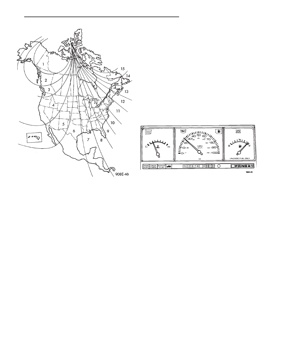
Fig. 3 Variance Zone Map
Fig. 4 Overhead Console Connector
Ä
OVERHEAD CONSOLE
8C - 23