Chrysler Le Baron, Dodge Dynasty, Plymouth Acclaim. Manual - part 286
(Fig. 9). This short circuits the electrodes. Spark
plugs with electrode gap bridging can be cleaned us-
ing standard procedures.
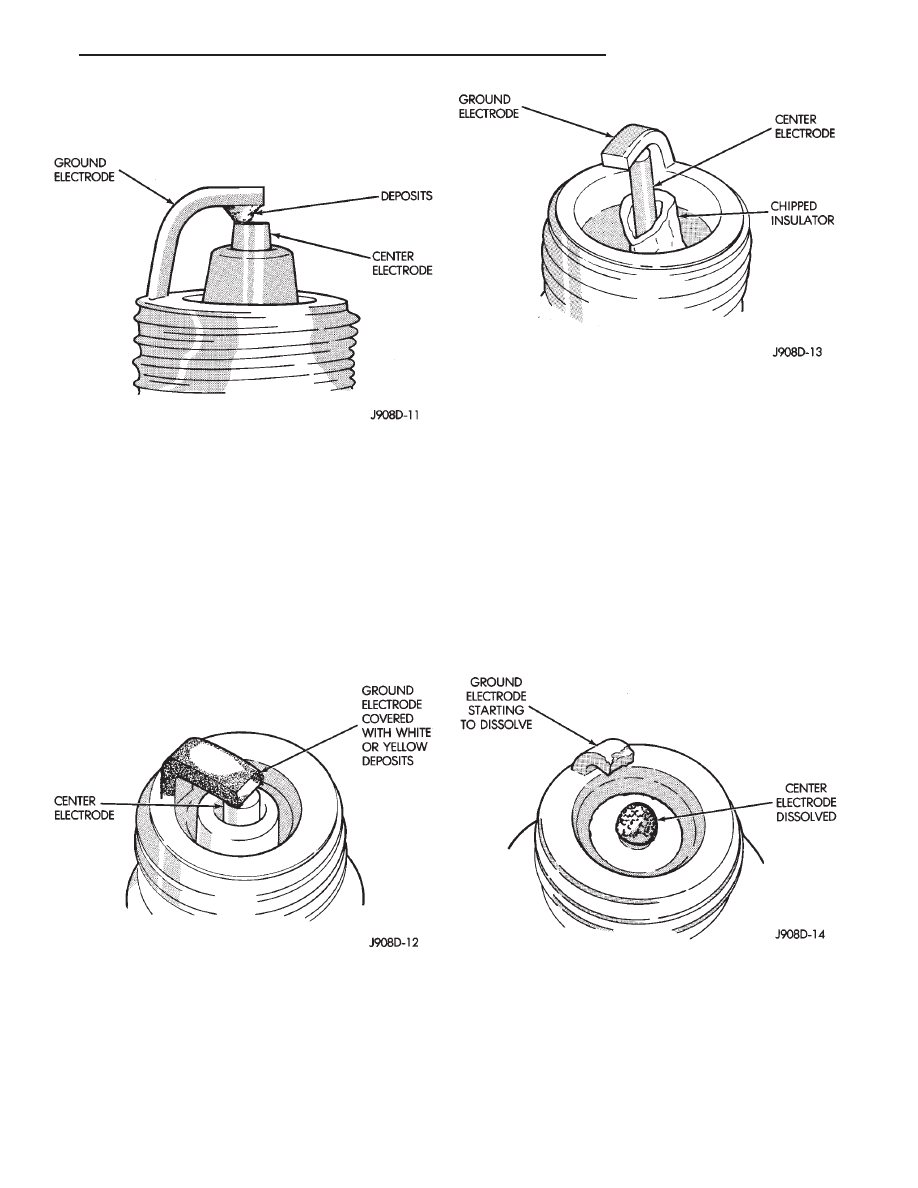
SCAVENGER DEPOSITS
Fuel scavenger deposits may be either white or yel-
low (Fig. 10). They may appear to be harmful, but
are a normal condition caused by chemical additives
in certain fuels. These additives are designed to
change the chemical nature of deposits and decrease
spark plug misfire tendencies. Accumulation on the
ground electrode and shell area may be heavy but
the deposits are easily removed. Spark plugs with
scavenger deposits can be considered normal in con-
dition and be cleaned using standard procedures.
CHIPPED ELECTRODE INSULATOR
A chipped electrode insulator usually results from
bending the center electrode while adjusting the
spark plug electrode gap. Under certain conditions,
severe detonation also can separate the insulator
from the center electrode (Fig. 11). Replace spark
plugs with chipped electrode insulators.
PREIGNITION DAMAGE
Excessive combustion chamber temperature can
cause preignition damage. The center electrode dis-
solves first and the ground electrode dissolves some-
what later (Fig. 12). Insulators appear relatively
deposit free. Determine if the spark plug has the cor-
rect heat range rating for the engine, if ignition tim-
ing is over advanced or if other operating conditions
are causing engine overheating. The heat range rat-
ing refers to the operating temperature of a particu-
lar type spark plug. Spark plugs are designed to
operate within specific temperature ranges depend-
ing upon the thickness and length of the center elec-
trode and porcelain insulator.
SPARK PLUG OVERHEATING
Overheating is indicated by a white or gray center
electrode insulator that also appears blistered (Fig.
13). The increase in electrode gap will be consider-
ably in excess of 0.001 in per 1000 miles of operation.
This suggests that a plug with a cooler heat range
rating should be used. Over advanced ignition tim-
Fig. 9 Electrode Gap Bridging
Fig. 10 Scavenger Deposits
Fig. 11 Chipped Electrode Insulator
Fig. 12 Preignition Damage
Ä
IGNITION SYSTEMS
8D - 5