Chrysler Le Baron, Dodge Dynasty, Plymouth Acclaim. Manual - part 288


  Index      Chrysler     Chrysler Le Baron, Dodge Dynasty, Plymouth Acclaim - service repair manual 1993 year


Search            


Content   ..  286  287  288  289   ..


Chrysler Le Baron, Dodge Dynasty, Plymouth Acclaim. Manual - part 288


(10) If no spark is produced, replace the ignition coil.

POOR PERFORMANCE TEST

To prevent unnecessary diagnostic time and

possible incorrect results, the Testing For Spark
At Coil procedure should be performed before
this test.

WARNING: APPLY PARKING BRAKE AND/OR BLOCK
THE WHEELS BEFORE PERFORMING ANY ENGINE
RUNNING TESTS.

Check and adjust basic timing (refer to the specifica-

tion section of this group and see service procedures).

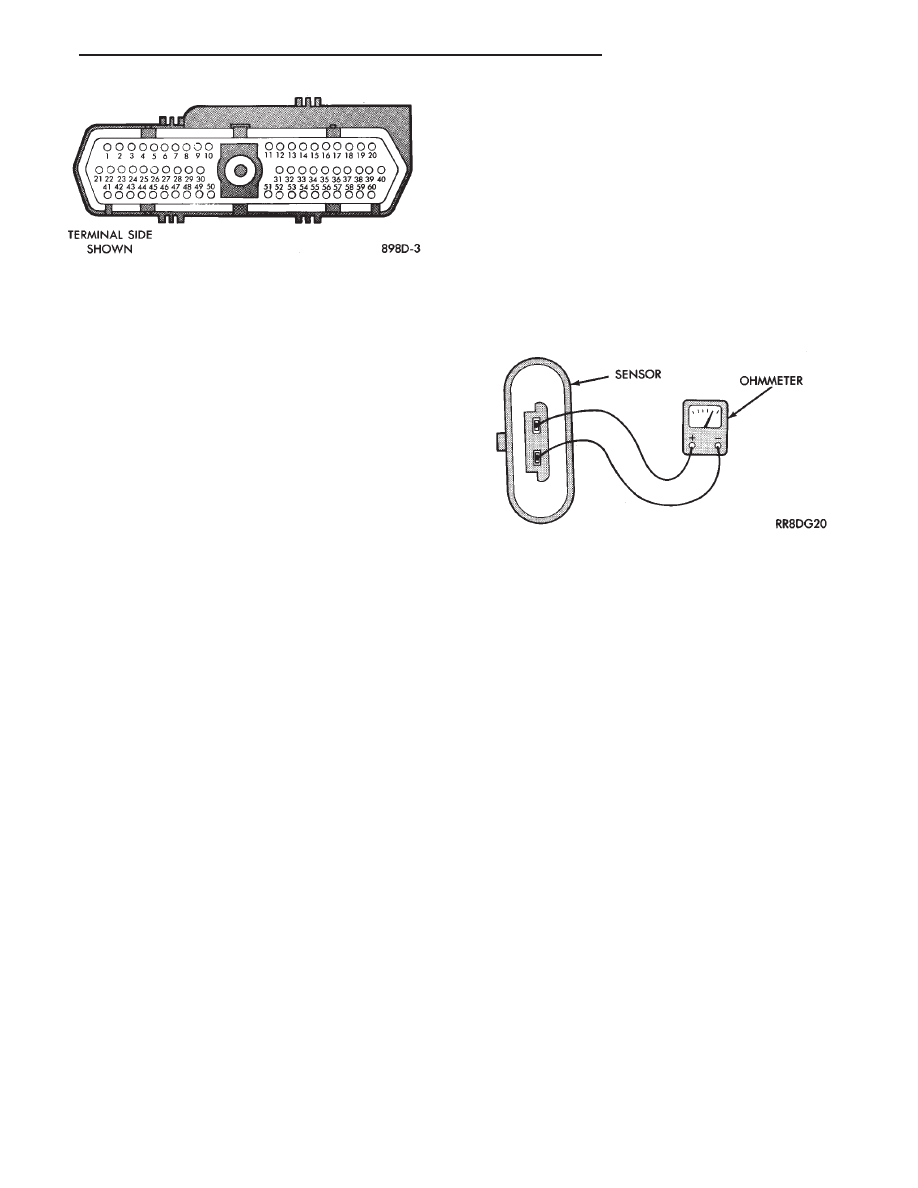
COOLANT TEMPERATURE SENSOR TEST

(1) With key off, disconnect wire connector from

coolant temperature sensor (Fig. 6).

(2) Connect one lead of ohmmeter to one terminal of

coolant temperature sensor.

(3) Connect the other lead of ohmmeter to remaining

terminal of coolant temperature sensor. The ohmmeter
should read as follows;
• Engine/Sensor at normal operating temperature
around 200°F should read approximately 700 to 1,000
ohms.
• Engine/Sensor at room temperature around 70°F,
ohmmeter should read approximately 7,000 to 13,000
ohms.

Refer to On Board Diagnostics in the General

Diagnosis section of Group 14. Also, refer to the
DRBII scan tool and the appropriate Powertrain
Diagnostic Procedures manual for additional
test procedures.

MANIFOLD ABSOLUTE PRESSURE (MAP) SENSOR
TEST

Refer to the DRB II scan tool and appropriate Pow-

ertrain Diagnostic Procedures manual for further test
procedures.

Fig. 5 60-Way Electrical Connector, Powertrain con-

trol module

Fig. 6 Coolant Temperature Sensor Test

Ä

IGNITION SYSTEMS

8D - 13

2.2L TBI, 2.5L TBI, 2.5L MPI AND 3.0L IGNITION SYSTEMS—SERVICE

PROCEDURES

INDEX

page

page

Coolant Temperature Sensor

. . . . . . . . . . . . . . . . 14

Distributor Pick-Up—2.2L TBI, 2.5L TBI and

2.5L MPI Engines

. . . . . . . . . . . . . . . . . . . . . . . 18

Distributor Service—3.0L Engine

. . . . . . . . . . . . . 18

Distributor—2.2L TBI, 2.5L TBI and 2.5L MPI

Engines

. . . . . . . . . . . . . . . . . . . . . . . . . . . . . . 17

Idle RPM Test—2.5L and 3.0L Engines

. . . . . . . . 16

Ignition Coil—2.2L TBI, 2.5L TBI and

2.5L MPI Engines

. . . . . . . . . . . . . . . . . . . . . . . 14

Ignition Coil—3.0L Engines

. . . . . . . . . . . . . . . . . 15

Ignition Timing Procedure—2.2L TBI, 2.5L TBI,

2.5L MPI, and 3.0L Engines

. . . . . . . . . . . . . . . 16

Manifold Absolute Pressure (MAP) Sensor

Service—2.5L TBI and 3.0L Engines

. . . . . . . . 22

Powertrain Control Module (PCM)

. . . . . . . . . . . . 14

Spark Plug Service

. . . . . . . . . . . . . . . . . . . . . . . 15

POWERTRAIN CONTROL MODULE (PCM)

The powertrain control module (PCM) is located

next to the battery (Fig. 1).

REMOVAL

(1) Remove air cleaner duct or air cleaner assem-

bly.

(2) Remove battery.
(3) Remove PCM mounting screws.
(4) Remove 60-way wiring connector from the

PCM.

(5) Remove PCM.

INSTALLATION

(1) Connect 60-Way electrical connector to PCM

(Fig. 1).

(2) Install PCM. Tighten mounting screws.
(3) Install battery.
(4) Install air cleaner duct or air cleaner assembly.

COOLANT TEMPERATURE SENSOR

On 2.2L TBI, 2.5L TBI and 2.5L MPI (flexible fuel

AA-Body) engines, the coolant temperature sensor is
located behind the ignition coil (Fig. 2). On 3.0L en-
gines the sensor is located next to the thermostat
housing (Fig. 3).

REMOVAL

(1) Drain cooling system until coolant level is below

coolant sensor. Refer to Group 7, Cooling System.

(2) Disconnect electrical connector from sensor.
(3) Remove sensor from engine.

INSTALLATION

(1) Install coolant sensor. Tighten 2.2L TBI, 2.5L

TBI or 2.5L MPI engine coolant sensor to 28 N

Im (20

ft. lbs.) torque. Tighten the 3.0L engine coolant sensor
to 7 N

Im (60 in. lbs.) torque.

(2) Connect electrical connector to sensor.
(3) Fill cooling system. Refer to Group 7, Cooling

System.

IGNITION COIL—2.2L TBI, 2.5L TBI AND 2.5L MPI
ENGINES

The ignition coil mounts to the thermostat housing

(Fig. 4).

Fig. 1 Powertrain control module (PCM)

Fig. 2 Coolant Temperature Sensor—2.2 TBI, 2.5L

TBI and 2.5L MPI Engines

8D - 14

IGNITION SYSTEMS

Ä

REMOVAL

(1) Disconnect the coil to distributor ignition cable

(Fig. 4).

(2) Disconnect the wiring harness connector from

the coil.

(3) Remove ignition coil mounting screws.

INSTALLATION

(1) Install ignition coil onto the bracket. Tighten

the screws to 9.5 N

Im (85 in. lbs.) torque.

(2) Connect the wiring harness connector.
(3) Connect the coil to distributor ignition cable.

IGNITION COIL—3.0L ENGINES

The ignition coil is located at the back of the intake

manifold (Fig. 5).

REMOVAL

(1) Remove air cleaner assembly.
(2) Disconnect ignition cable from coil.
(3) Disconnect wiring harness connector from coil.
(4) Remove coil mounting screws.

INSTALLATION

(1) Loosely install ignition coil on intake manifold.

Tighten the intake manifold fastener to 13 N

Im (115

in. lbs.) torque. Tighten ignition coil bracket fasteners
to 10 N

Im (96 in. lbs.) torque.

(2) Connect the wiring harness connector.
(3) Connect the coil to distributor ignition cable.
(4) Install the air cleaner assembly. Tighten the air

cleaner fasteners to 25 N

Im (225 in. lbs.) torque.

SPARK PLUG SERVICE

When replacing the spark plug and coil cables, route

the cables correctly and secure them in the appropriate
retainers. Incorrectly routed cables can cause the radio
to reproduce ignition noise. It can also cause cross
ignition of the spark plugs or short circuit the cables to
ground.

SPARK PLUG REMOVAL

Always remove cables by grasping at boot, rotating

the boot 1/2 turn, and pulling straight back in a steady
motion.

(1) Prior to removing the spark plug spray com-

pressed air around the spark plug hole and the area
around the spark plug.

(2) Remove the spark plug using a quality socket

with a rubber or foam insert.

Fig. 3 Coolant Temperature Sensor—3.0L Engine

Fig. 4 Ignition Coil—2.2L TBI, 2.5L TBI and 2.5L MPI

Engines

Fig. 5 Ignition Coil—3.0L Engine

Ä

IGNITION SYSTEMS

8D - 15

(3) Inspect the spark plug condition. Refer to Spark

Plug Condition in this section.

SPARK PLUG GAP ADJUSTMENT

Check the spark plug gap with a gap gauge. If the

gap is not correct, adjust it by bending the ground
electrode (Fig. 6).

SPARK PLUG INSTALLATION

(1) Start the spark plug into the cylinder head by

hand to avoid cross threading.

(2) Tighten spark plugs to 28 N

Im (20 ft. lbs.)

torque.

(3) Install spark plug cables over spark plugs.

IDLE RPM TEST—2.5L AND 3.0L ENGINES

WARNING: APPLY PARKING BRAKE AND/OR BLOCK
WHEELS BEFORE PERFORMING IDLE CHECK OR
ADJUSTMENT, OR ANY TESTS WITH A RUNNING
ENGINE.

Engine idle set rpm should be recorded when the

vehicle is first brought into shop for testing. This
will assist in diagnosing complaints of engine stalling,
creeping and hard shifting on vehicles equipped with
automatic transaxles.

Proceed to the Throttle Body Minimum Airflow pro-

cedures in Group 14.

IGNITION TIMING PROCEDURE—2.2L TBI, 2.5L
TBI, 2.5L MPI, AND 3.0L ENGINES

WARNING: APPLY PARKING BRAKE AND/OR BLOCK
WHEELS BEFORE PERFORMING SETTING IGNITION
TIMING OR PERFORMING ANY TEST ON AN OPER-
ATING ENGINE.

Proper ignition timing is required to obtain optimum

engine performance. The distributor must be correctly
indexed to provide correct initial ignition timing.

(1) Set the gearshift selector in park or neutral and

apply the parking brake. All lights and accessories
must be off.

(2) If using a magnetic timing light, insert the

pickup probe into the open receptacle next to the
timing scale window. If a magnetic timing unit is not
available, use a conventional timing light connected to
the number one cylinder spark plug cable.

Do not puncture cables, boots or nipples with

test probes. Always use proper adapters. Punc-
turing the spark plug cables with a probe will
damage the cables. The probe can separate the
conductor and cause high resistance. In addition
breaking the rubber insulation may permit sec-
ondary current to arc to ground.

(3) Turn selector switch to the appropriate cylinder

position.

(4) Start engine and run until operating tempera-

ture is obtained.

(5) With the engine at normal operating tempera-

ture, connect the DRBII scan tool to the data link
connector (diagnostic connector). Access the State Dis-
play screen. Refer to the appropriate Powertrain Diag-
nostics Procedures Manual. If not using the DRBII
scan tool, disconnect the coolant temperature
sensor electrical connector. 
The electric radiator
fan will operate and the malfunction indicator lamp
(instrument panel Check Engine light) will turn on
after disconnecting the coolant sensor or starting the
DRBII scan tool procedure.

(6) Aim Timing Light at timing scale (Fig. 7 or Fig.

8) or read magnetic timing unit. If flash occurs when
timing mark is before specified degree mark, timing is
advanced. To adjust, turn distributor housing in direc-
tion of rotor rotation.

If flash occurs when timing mark is after specified

degree mark, timing is retarded. To adjust, turn dis-
tributor housing against direction of rotor rotation.
Refer to Vehicle Emission Control Information label for
correct timing specification. If timing is within

6 2° of

value specified on the label, proceed to step (8). If
outside specified tolerance, proceed to next step.

(7) Loosen

distributor

hold-down

arm

screw

enough to rotate the distributor housing (Fig. 9 or

Fig. 6 Setting Spark Plug Gap—Typical

8D - 16

IGNITION SYSTEMS

Ä


Content   ..  286  287  288  289   ..