Chrysler Le Baron, Dodge Dynasty, Plymouth Acclaim. Manual - part 251


  Index      Chrysler     Chrysler Le Baron, Dodge Dynasty, Plymouth Acclaim - service repair manual 1993 year


Search            


Content   ..  249  250  251  252   ..


Chrysler Le Baron, Dodge Dynasty, Plymouth Acclaim. Manual - part 251


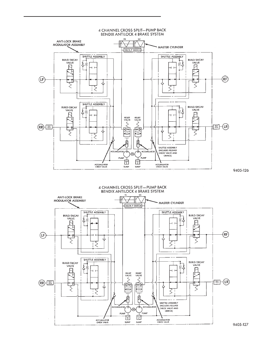
Fig. 1 Normal Braking - Hydraulic Control

Fig. 2 Build Pressure - Hydraulic Control (Left Front Wheel Shown)

Ä

ANTILOCK 4 BRAKE SYSTEM

5 - 21

ABS BRAKING-DECAY PRESSURE

BUILD/DECAY VALVES

Open, allowing release of brake fluid pressure

through the decay valve to the modulator sump. This
brake fluid then gets pumped into the accumulator
for the build pressure cycle (Fig. 3).

BENDIX ANTILOCK 4 BRAKE SYSTEM
DIAGNOSTICS

GENERAL INFORMATION

WARNING: SOME OPERATIONS IN THIS SECTION
REQUIRE THAT HYDRAULIC TUBES, HOSES AND
FITTINGS BE DISCONNECTED FOR INSPECTION
OR TESTING PURPOSES.

CAUTION: REVIEW THIS ENTIRE SECTION PRIOR
TO PERFORMING ANY MECHANICAL WORK ON A
VEHICLE EQUIPPED WITH THE BENDIX ANTILOCK
4 BRAKE SYSTEM. THIS SECTION CONTAINS IN-
FORMATION ON PRECAUTIONS PERTAINING TO
POTENTIAL COMPONENT DAMAGE, VEHICLE DAM-
AGE AND PERSONAL INJURY WHICH COULD RE-
SULT

WHEN

SERVICING

AN

ABS

EQUIPPED

VEHICLE.

CAUTION: Certain components of ABS brake sys-
tem are not intended to be serviced individually. At-
tempting to remove or disconnect certain system
components, may result in personal injury and/or
improper system operation. Only those components
with approved removal and installation procedures
in this manual should be serviced.

This section contains information necessary to di-

agnosis mechanical conditions which can affect oper-
ation of the Bendix Antilock 4 Brake System.
Specifically, this section should be used to help diag-
nose mechanical conditions which result in any of
the following:

(1) Anti-Lock Warning Lamp turned on.
(2) Brakes Lock on Hard Application
Vehicle conditions which are obviously mechanical

in nature, such as noise, pulsation, no power assist,
turning on of the Red Brake Warning Lamp or vibra-
tion during normal braking. Should be directed to
Group 5 Brakes in the Front Wheel Drive, Chassis
service manual.

To effectively diagnose and repair conditions affect-

ing the Bendix Antilock 4 Brake System, it is impor-
tant to read and understand the Antilock Brake
System Functional Description. The Bendix Antilock
4 Brake System Functional Description is explained

Fig. 3 Decay Pressure - Hydraulic Control (Left Front Wheel Shown)

5 - 22

ANTILOCK 4 BRAKE SYSTEM

Ä

earlier in this service manual supplement. Then follow
the diagnostic procedures outlined in this section.

Many conditions that generate customer complaints

may be normal operating conditions, but are judged to
be a problem due to not being familiar with the ABS
system. These conditions can be recognized without
performing extensive diagnostic work, given adequate
understanding of the operating principles and perfor-
mance characteristics of the ABS system.

DEFINITIONS

Several abbreviations are used in this manual. They

are presented here for reference.
• CAB—Controller Antilock Brake

• ABS—Antilock Brake System

• PSI—Pounds per Square Inch (pressure)

• WSS—Wheel Speed Sensor

• AC—Alternating Current

ABS COMPUTER SYSTEM SERVICE PRECAUTIONS

The ABS system uses an electronic control module,

the CAB. This module is designed to withstand normal
current draws associated with vehicle operation. How-
ever care must be taken to avoid overloading the CAB
circuits. In testing for open or short circuits, do
not ground or apply voltage to any of the circuits
unless instructed to do so by the appropriate
diagnostic procedure. 
These circuits should only be
tested using a high impedance multi-meter, special
tools or the DRB II tester as described in this section.
Power should never be removed or applied to any
control module with the ignition in the ON position.
Before removing or connecting battery cables, fuses, or
connectors, always turn the ignition to the OFF posi-
tion.

ABS GENERAL SERVICE PRECAUTIONS

TEST DRIVING ABS COMPLAINT VEHICLES

Most ABS complaints will require a test drive as a

part of the diagnostic procedure. The purpose of the
test drive is to duplicate the condition.

Remember conditions that result in the turn-

ing on of the Red Brake Warning Lamp may
indicate reduced braking ability. The following
procedure should be used to test drive an ABS
complaint vehicle.

Before test driving a brake complaint vehicle, note

whether the Red or Amber Brake Warning Lamp is
turned on. If the Red Brake Warning Lamp, is
turned on, refer to the base brake Control Valves
Section in the Front Wheel Drive, chassis service
manual. If the Amber Antilock Warning light was or
is on, read record and erase the faults. While the
Amber ABS Warning Lamp is on the ABS system is
not functional. The standard brake system and abil-

ity to stop the car is not affected, if only the Amber
Antilock Warning Lamp is on.

(1) Turn ignition key to the off position and then

back to the on position. Note whether the Amber ABS
Warning Lamp continues to stay on. If it does refer to
the 1994 Bendix Antilock 4 Brake System Diagnostic
Manual for the required diagnostic test procedures.

(2) If the Amber ABS Warning Lamp goes out, shift

vehicle into gear and drive car to a speed of 5 mph to
complete the ABS drive-off cycle. If at this time, the
Amber ABS Warning Lamp goes on refer to the 1994
Bendix Antilock 4 Brake System Diagnostic Manual.

(3) If the Amber ABS Warning Lamp remains OUT,

continue to drive the vehicle a short distance. During
this test drive be sure that the vehicle achieves at least
25 mph. Brake to at least one complete stop and again
accelerate to 25 mph.

(4) If a functional problem with the ABS system is

determined while test driving a vehicle. Refer to the
Bendix Antilock 4 Brake System Diagnostics Manual
for required diagnostic test procedures and proper use
of the DRB II tester.

ABS BRAKE SYSTEM ON VEHICLE SERVICE

The following are general precautions which

should be observed whenever servicing and or
diagnosing the ABS system and other vehicle
electronic systems. Failure to observe these pre-
cautions may result in ABS system damage.

(1) If welding work is to be performed on a vehicle

using an arc welder. The wiring harness connector
should be disconnected from the CAB before beginning
any welding operation.

(2) The CAB 60 way connector and modulator as-

sembly 10 way connector, should never be connected or
disconnected with the ignition in the on position.

(3) Some components of Bendix Antilock 4 Brake

System assemblies can not be serviced separately from
the assembly and will require replacement of the
complete assembly for servicing. Do not disassemble
any component which is designated as non-serviceable.

CAUTION: Brake fluid will damage painted surfaces.
If brake fluid is spilled on any painted surfaces, wash
off with water immediately.

WHEEL SPEED SENSOR CABLES

Proper installation and routing of the Wheel Speed

Sensor Cables is critical to continued system opera-
tion. Be sure that cables are installed, routed and
clipped properly. Failure to install speed sensor ca-
bles as shown in the on car service section of this

Ä

ANTILOCK 4 BRAKE SYSTEM

5 - 23

manual. May result in contact with moving parts or
over extension of cables, resulting in component fail-
ure and an open circuit.

MECHANICAL DIAGNOSTICS AND SERVICE
PROCEDURES

SPECIAL SERVICE TOOL

Some diagnostic procedures in this section require

the use of the DRB diagnostics tester. The proper ap-
plication and procedures for the use of this tool are
described below.

DRB DIAGNOSTIC TESTER

Some of the diagnostic procedures that are ex-

plained in this section require the use of the DRB Di-
agnostics Tester to insure that proper diagnostics are
performed. Refer to those sections for proper testing
procedures and the DRB operators manual for its
proper operational information.

INTERMITTENT FAULTS

As with virtually any electronic system, intermit-

tent faults in the ABS system may be difficult to ac-
curately diagnose.

Most intermittent faults are caused by faulty elec-

trical connections or wiring. When an intermittent
fault is encountered, check suspect circuits for:

(1) Poor mating of wiring harness connector halves

or terminals not fully seated in the connector body.

(2) Improperly formed or damaged terminals. All

connector terminals in a suspect circuit should be
checked and carefully reformed to increase contact
tension with its mating terminal.

(3) Poor terminal to wire connection. This requires

removing the terminal from the connector body to in-
spect.

(4) Pin presence in the connector assembly
(5) Connector push-in, spread, and corrosion.
If a visual check does not find the cause of the

problem, operate the car in an attempt to duplicate
the condition and record the set Fault code.

Most failures of the ABS system will disable the

Antilock function for the entire ignition cycle even if
the fault clears before key-off. There are some failure
conditions, however, which will allow ABS operation
to resume during the ignition cycle in which it oc-
curred, if the failure condition is no longer present.
The following conditions may result in intermittent
illumination of the Amber Antilock Warning Lamp.
All other failures will cause the lamp to remain on
until the ignition switch is turned off. Circuits in-
volving these inputs to the CAB should be investi-
gated if a complaint of intermittent warning system
operation is encountered.

(1) Low system voltage: If Low System Voltage is

detected by the CAB, the CAB will turn on the Am-
ber Antilock Warning Lamp until normal system

voltage is achieved. Once normal voltage is seen at
the CAB, normal operation resumes.

(2) Antilock system and pump/motor relay. If the

relays fail to make the ground circuit connection or
has an intermittent ground. The CAB will turn on
the Amber Antilock Warning Light.

(3) Excess decay, an extended pressure decay pe-

riod, will turn on the Amber Antilock Warning Light
until the vehicle comes to a complete stop.

Additionally, any condition which results in inter-

ruption of electrical current to the CAB or modulator
assembly, may cause the Amber Antilock Warning
Lamp to turn on intermittently.

ABS BRAKE SYSTEM DIAGNOSTIC FEATURES

ABS SYSTEM SELF DIAGNOSIS

The ABS system is equipped with a self diagnostic

capability which may be used to assist in isolation of
ABS faults. The features of the self diagnostics sys-
tem are described below.

START-UP CYCLE

The self diagnostic ABS start up cycle begins when

the ignition switch is turned to the on position. An
electrical check is completed on the ABS components.
Such as Wheel Speed Sensor Continuity and System
and other Relay continuity. During this check the
Amber Antilock Light is turned on for approximately
1- 2 seconds.

Further Functional testing is accomplished once

the vehicle is set in motion, known as drive-off.
• The solenoid valves and the pump/motor are acti-
vated briefly to verify function.
• The voltage output from the wheel speed sensors is
verified to be within the correct operating range.

If the vehicle is not set in motion within 3 minutes

from the time the ignition switch is set in the on po-
sition. The solenoid test is bypassed but the pump/
motor is activated briefly to verify that it is
operating correctly.

CONTROLLER ANTILOCK BRAKE CAB

Fault codes are kept in a Non-Volatile memory un-

til either erased by the technician using the DRB or
erased automatically after 50 ignition cycles (key
ON-OFF cycles). The only fault that will not be
erased after 50 (KEY CYCLES) is the CAB fault. A
CAB fault can only be erased by the technician using
the DRB diagnostic tester. More than one fault can
be stored at a time. The number of key cycles since
the most recent fault was stored is also displayed.
Most functions of the CAB and ABS system can be
accessed by the technician for testing and diagnostic
purposes by using the DRB.

5 - 24

ANTILOCK 4 BRAKE SYSTEM

Ä


Content   ..  249  250  251  252   ..