Chrysler Le Baron, Dodge Dynasty, Plymouth Acclaim. Manual - part 250


  Index      Chrysler     Chrysler Le Baron, Dodge Dynasty, Plymouth Acclaim - service repair manual 1993 year


Search            


Content   ..  248  249  250  251   ..


Chrysler Le Baron, Dodge Dynasty, Plymouth Acclaim. Manual - part 250


fice (restriction) in the line between the wheel and
the Build/Decay Valve. This restriction provides a
controlled build rate to each wheel brake during an
Antilock stop. The Shuttle Orifice Valve will remain
in the orificed position until the ABS cycle is com-
plete. When the ABS cycle has been completed the
Build/Decay valves will return to their released posi-
tion which will equalize the pressure across the
Shuttle Orifice Valves. When the pressure equalizes,
the spring loaded Shuttle Orifice valves will return
to the unrestricted position.

FLUID SUMPS

There are two Fluid Sumps in the Hydraulic As-

sembly, one for the primary and secondary hydraulic
circuits. The Fluid Sumps store the brake fluid that
is decayed from the wheel brakes during an ABS cy-
cle. This fluid is then pumped to an accumulator
and/or the hydraulic system in order to provide build
pressure. The typical pressure in the sumps is 50 psi,
during ABS operation only.

HYDRAULIC SPRING ACCUMULATOR

The Hydraulic Spring Accumulators (Fig. 3) (one

on each circuit) are used to store pressurized hydrau-
lic brake fluid during ABS operation only. This fluid
is used during hard braking when the ABS system is
activated, to supplement brake pressure when re-
quired. During normal Non ABS brake operation
there is NO pressurized brake fluid stored in the ac-
cumulators. The Hydraulic Spring Accumulators are
not a serviceable part of the Modulator Assembly
and should never be removed from the assembly.

PRESSURE DIFFERENTIAL SWITCH

The Pressure Differential Switch on the Bendix An-

tilock 4 Brake System is located on the frame rail
mounted brake hydraulic tube junction block. This
switch functions the same as the Pressure Differential
Switch located in the combination valve on standard
non ABS brake system. The pressure differential
switch monitors the primary and secondary hydraulic
brake circuits for a difference in pressure. A pressure
difference greater than 225 psi., will move and latch
the switch, grounding the Red Brake Warning Light
circuit. This will in turn, turn on the Red Brake
Warning Light in the instrument panel to warn the
driver of a pressure loss in one of the brake hydraulic
systems. This pressure differential switch is a replace-
able item of the junction block assembly. The Red
Brake Warning Light only indicates a problem
with the foundation brake hydraulic system and
not the Antilock system.

PUMP/MOTOR ASSEMBLY

The Modulator Assembly contains 2 Pump Assem-

blies, one each for the primary and secondary hydrau-
lic circuits. Both pumps are driven by a common
electric motor which is part of the Modulator Assembly.
The pumps take brake fluid from the sumps to supply
pressure to the accumulators or hydraulic system via
the shuttle orifice during an Antilock stop. The motor
only runs during an ABS stop and is controlled by the
CAB via the Pump/Motor Relay. The Pump/Motor
Assembly is not a serviceable item. If it requires
service the Modulator Assembly must be replaced.

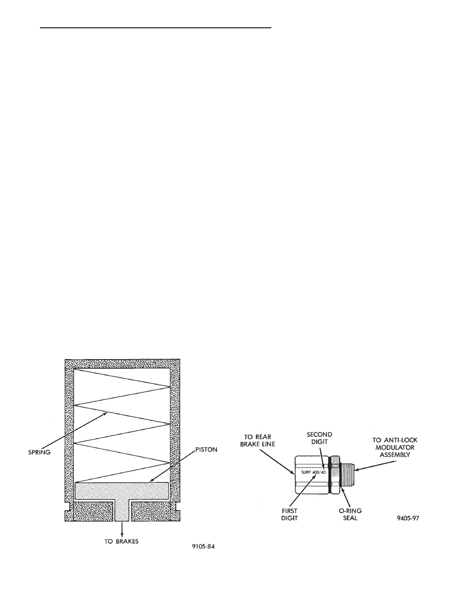
PROPORTIONING VALVES

Two Proportioning Valves (Fig. 4) are used in the

Bendix Antilock 4 Brake System, one for each of the
rear wheel brake hydraulic circuits. The Proportioning
Valves function the same as in a standard brake
system. The Proportioning Valves are located on the
side of the modulator assembly (Fig. 1). Each rear
wheel hydraulic brake line, is connected to an indi-
vidual proportioning valve.

Fig. 3 Hydraulic Spring Accumulator

Fig. 4 Proportioning Valve Identification

Ä

ANTILOCK 4 BRAKE SYSTEM

5 - 17

WHEEL SPEED SENSORS

One Wheel Speed Sensor (WSS), is located at each

wheel (Fig. 5 and 6), and sends a small AC signal to the
control module CAB. This signal is generated by mag-
netic induction. The magnetic induction is created,
when a toothed sensor ring (Tone Wheel) (Fig. 7) passes
a stationary magnetic Wheel Speed Sensor. The CAB
converts the AC signal generated at each wheel into a
digital signal. If a wheel locking tendency is detected,
the CAB will then modulate hydraulic pressure to pre-
vent the wheel or wheels from locking.

The front Wheel Speed Sensor is attached to a boss

in the steering knuckle (Fig. 5). The tone wheel is
part of the outboard constant velocity joint (Fig. 5).

The rear Wheel Speed Sensor is mounted to the cal-
iper adapter (Fig. 6) and the rear tone wheel is an
integral part of the rear wheel hub (Fig. 7). The
speed sensor air gap is NOT adjustable.

The four Wheel Speed Sensors are serviced individ-

ually. The front Tone Wheels are serviced as an as-
sembly with the outboard constant velocity joint. The
rear Tone Wheels are serviced as an assembly with
the rear brake hub.

Correct Antilock system operation is dependent on

the vehicle’s wheel speed signals, that are generated
by the Wheel Speed Sensors. The vehicle’s wheels
and tires must all be the same size and type to gen-
erate accurate signals. In addition, the tires must be
inflated to the recommended pressures for optimum
system operation. Variations in wheel and tire size
or significant variations in inflation pressure can
produce inaccurate wheel speed signals.

CONTROLLER ANTILOCK BRAKE CAB

The Antilock Brake Controller is a small micropro-

cessor based device which monitors the brake system
and controls the system while it functions in the An-
tilock mode. The CAB is mounted on the top of the
right front frame rail and uses a 60-way system con-
nector (Fig. 8). The power source for the CAB is
through the ignition switch in the Run or On posi-
tion. THE CONTROLLER ANTILOCK BRAKE
CAB IS NOT ON THE CCD BUS

The primary functions of the CAB are:
(1) Detect wheel locking tendencies.
(2) Control fluid modulation to the brakes while in

Antilock mode.

(3) Monitor the system for proper operation.

Fig. 5 Front Wheel Speed Sensor

Fig. 6 Rear Wheel Speed Sensor

Fig. 7 Rear Tone Wheel (Typical)

5 - 18

ANTILOCK 4 BRAKE SYSTEM

Ä

(4) Provide communication to the DRB II while in

the Antilock brakes diagnostic mode.

The CAB continuously monitors the speed of each

wheel, through the signals generated at the Wheel
Speed Sensors. This is used to determine if any
wheel of the vehicle is beginning to lock-up (skid)
when the brakes are applied. When a wheel locking
tendency is detected during brake apply. The CAB
commands the appropriate Build/Decay valves to
modulate brake fluid pressure in some or all of the
hydraulic circuits. The CAB continues to control
pressure in individual hydraulic circuits until a lock-
ing tendency is no longer present.

The ABS system is constantly monitored by the

CAB for proper operation. If the CAB detects a fault,
it will turn on the Amber Antilock Warning Lamp
and disable the ABS brake system. The normal Non
ABS brake system will remain operational.

The CAB contains a self-diagnostic program which

will turn on the Amber Antilock Warning Lamp
when a system fault is detected. Faults are stored in
a diagnostic program memory. There are 16 fault
codes which may be stored in the CAB and displayed
through the DRB II. These fault codes will remain in
the CAB memory even after the ignition has been
turned off. The fault codes can be cleared by using
the DRB II diagnostics tester, or they will be auto-
matically cleared from the memory after (50) ignition
switch on/off cycles.

CONTROLLER ANTILOCK BRAKE (INPUTS)

• Four wheel speed sensors.

• Stop lamp switch.

• Ignition switch.

• System relay voltage.

• Ground.

• Pump/Motor Relay Monitor

• Diagnostics Communications

CONTROLLER ANTILOCK BRAKE (OUTPUTS)

• 4 Build/Decay valves.

• Antilock warning lamp.

• System relay actuation.

• Diagnostic communication.

• Pump/Motor relay actuation

DIAGNOSTIC CONNECTOR

The Bendix Antilock 4 Brake System diagnostic

connector is located under the fuse panel access
cover. The access cover is located on the lower sec-
tion of the instrument panel to the left side of the
steering column. The diagnostics connector is a blue
6 way connector see (Fig. 9).

ANTILOCK SYSTEM RELAYS AND WARNING LAMPS

SYSTEM RELAY

The ABS Modulator Valves are powered through

the System Relay which is located on a bracket
mounted to the CAB (Fig. 10). The System Relay
provides power to the CAB for modulator valve oper-
ation (pins 47 and 41) after the startup cycle when
the ignition is turned on.

Fig. 8 CAB Location

Fig. 9 Antilock Diagnostic Connector Location

Fig. 10 System Relay Location On The CAB

Ä

ANTILOCK 4 BRAKE SYSTEM

5 - 19

ANTILOCK WARNING LAMP DIODE

The Warning Lamp Relay on the Bendix Antilock

4 Brake System has been replaced with a diode. The
diode is used to control the function of the warning
lamp and is located inside the CAB module wiring
harness. The diode is a replaceable component of the
wiring harness, and will not require replacement of
the entire wiring harness if only the diode is diag-
nosed to have failed.

When the system relay is de-energized, the Anti-

lock warning lamp will be lit. This will occur because
a ground path exists for the Antilock warning lamp
through the Antilock warning lamp diode and the
system relay armature. When the system relay is en-
ergized by the CAB, the system relay armature will
no longer provide a ground and the lamp will turn
off. Thus, the lamp will be lit if either the CAB is
disconnected or a system fault causes the Antilock to
be turned off.

PUMP/MOTOR RELAY

Pump/Motor power is supplied by the Pump/Motor

Relay. The Pump/Motor Relay is either mounted on
the left front inner fender shield, or the front of the
left shock tower. The mounting location is dependent
on whether the vehicle is or is not equipped with a
power distribution center. See (Fig. 11 and 12) for
specific mounting locations.

ANTILOCK WARNING LAMP OFF

System Relay Energized
From pin 57, the CAB energizes the Antilock sys-

tem relay coil, thus the electrical current flow in the
coil closes the system relay. Then electrical current
is provided to pins 47 and 41 of the CAB to provide
power to the modulator valves.

The CAB turns off the Amber Antilock Warning

Lamp by breaking the ground path through pin 15 of
the CAB.

ANTILOCK WARNING LAMP ON

System Relay De-Energized.
When the Amber Antilock Warning Lamp is on,

there is no electrical current flow from the CAB at
pin 57 and the System Relay coil is NOT energized.
No electrical current flows to pin 47 and 41 (modula-
tor valve power), or to the Antilock Warning Lamp
diode. Thus, the Amber Antilock Warning Lamp is
not energized. The Amber Antilock Warning Lamp is
now grounded through the Antilock Warning Lamp
diode and pin 15 of the CAB turning on the Amber
Antilock Warning Lamp.

HYDRAULIC CIRCUITS AND VALVE OPERATION

Through the following operation descriptions and

diagrams. The function of the various hydraulic con-
trol valves in the ABS system will be described. The
fluid control valves mentioned below, control the flow
of pressurized brake fluid to the wheel brakes during
the different modes of Antilock braking.

For explanation purposes we will assume all speed

sensors are sending the same wheel speed informa-
tion, requiring the same hydraulic fluid modulation
at the same rate.

NORMAL BRAKING

BUILD/DECAY VALVES

Closed (Fig. 1)
The brake pedal is applied. The travel of the brake

pedal closes primary and secondary circuits from the
master cylinder fluid supply. Brake fluid from the
master cylinder primary and secondary circuits flows
through the build/decay valves to the wheel brakes.

ABS BRAKING-BUILD PRESSURE

BUILD/DECAY VALVES

Open (Fig. 2)

Fig. 11 Pump Motor Relay Location On AA Body

W/O Power Distribution Center

Fig. 12 Pump Motor Relay Location On AJ Body

With Power Distribution Center

5 - 20

ANTILOCK 4 BRAKE SYSTEM

Ä


Content   ..  248  249  250  251   ..