Chrysler Le Baron, Dodge Dynasty, Plymouth Acclaim. Manual - part 249
HYDRAULIC
BRAKE
LINE
ROUTING
WITH
BENDIX
ANTILOCK
4
BRAKE
SYSTEM
Ä
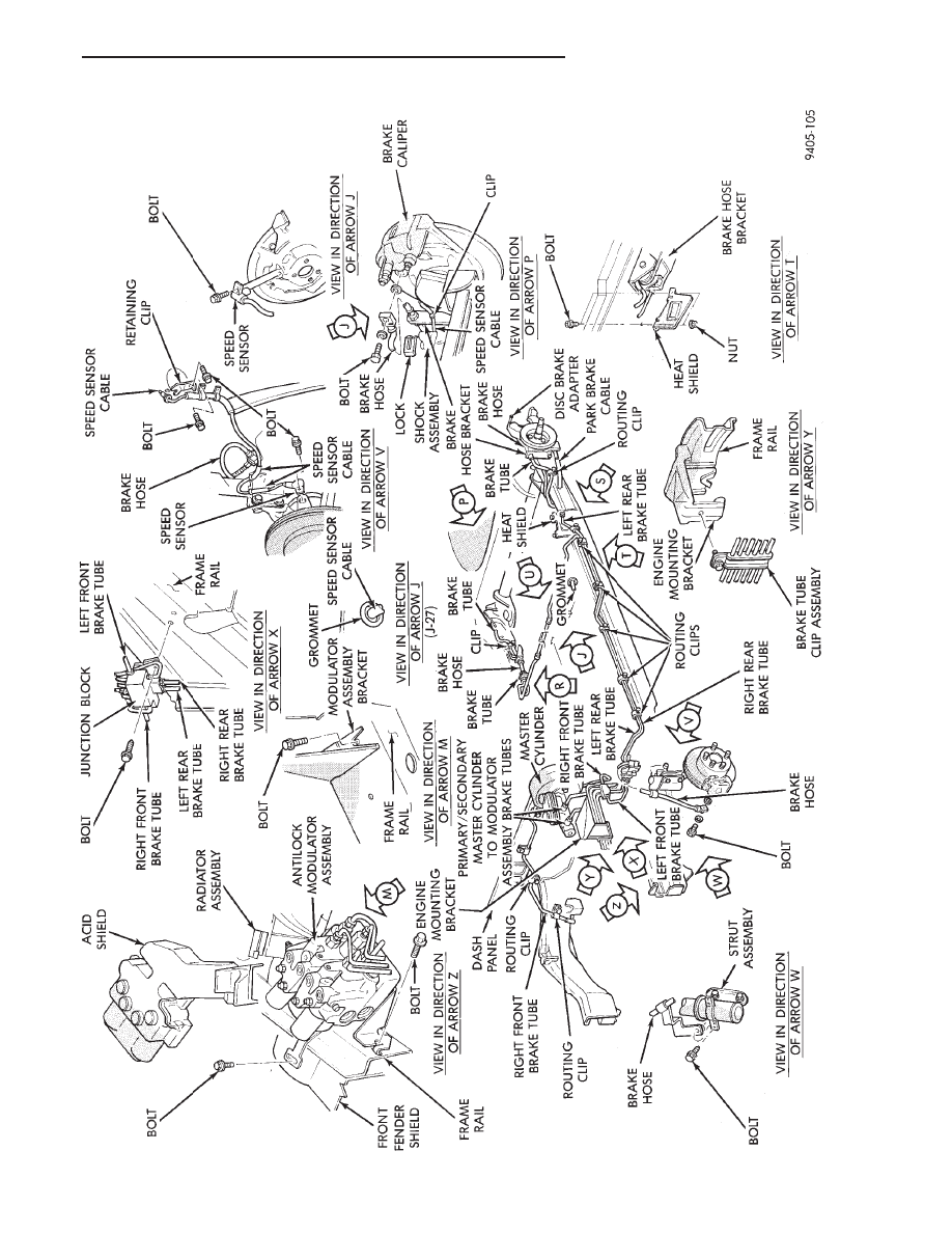
ANTILOCK 4 BRAKE SYSTEM
5 - 13
|
|
|
HYDRAULIC BRAKE LINE ROUTING WITH BENDIX ANTILOCK 4 BRAKE SYSTEM Ä ANTILOCK 4 BRAKE SYSTEM 5 - 13 |