Chrysler Le Baron, Dodge Dynasty, Plymouth Acclaim. Manual - part 200


  Index      Chrysler     Chrysler Le Baron, Dodge Dynasty, Plymouth Acclaim - service repair manual 1993 year


Search            


Content   ..  198  199  200  201   ..


Chrysler Le Baron, Dodge Dynasty, Plymouth Acclaim. Manual - part 200


HEATER-A/C UNIT ASSEMBLY—REMOVAL AND
INSTALLATION

AP, AC, AY BODY PROCEDURE

WARNING: IF EQUIPPED WITH A/C, THE REFRIG-
ERATION SYSTEM MUST BE COMPLETELY EMPTY
BEFORE PROCEEDING WITH THIS OPERATION.

(1) Disconnect battery NEGATIVE cable.
(2) Drain radiator and disconnect heater hoses at

unit. Tape heater tubes to keep from leaking during
removal. Refer to Group 7, Cooling System.

(3) Remove A/C condensate drain and disconnect

vacuum lines.

(4) Inside passenger compartment, perform as fol-

lows, according to body designation.

(a) AC-body, remove right upper and lower un-

der-panel silencers.

(b) AP & AC-bodies, remove steering column

cover.

(c) AC-body, remove left under-panel silencer.

(5) Position front seat or right front seat full rear.

(a) AP-body, remove right A-pillar trim.
(b) Remove right cowl side trim.

(6) Remove glove box.

(a) AC-body, remove right instrument panel re-

inforcement.
(7) AP-body only:

(a) Remove right instrument panel lower mount-

ing screw.

(b) Remove center bezel.
(c) Remove lower center module cover.
(d) Remove floor console.
(e) Remove instrument panel support brace (from

steering column opening to right cowl side at bot-
tom of instrument panel).

(f) Remove instrument panel to support bracket

(below glove box opening).

(g) Remove ash receiver.
(h) Remove radio.
(i) Remove panel top cover.
(j) Remove three right side panel to fence (below

windshield) attaching screws.
(8) AC-body, remove ash receiver.
(9) AP body, pull right lower side of instrument

panel rearward.

(10) Remove

center

distribution

and

defroster

adapter ducts.

(11) AP and AC-bodies, disconnect relay module.
(12) AP-body, remove instrument panel to unit

bracket.

(13) AP-body, remove lower air distribution duct.
(14) Disconnect blower motor wire connector.
(15) Disconnect demister hoses from top of unit.
(16) For Non-ATC equipped vehicles, disconnect

the temperature control cable flag from the bottom of
the heater-A/C unit. Then un-clip the cable from the
left side of the heat distribution duct. Swing the ca-
ble out of the way to the left. Disconnect the vacuum
lines at the unit.

(17) For ATC equipped vehicles, disconnect the in-

strument panel wiring from the rear face of the ATC
control unit.

(18) AC body, disconnect right 25-way connector

bracket and fuse block from panel.

(19) Fold floor right side carpet back (except AC

body).

(20) From engine compartment, remove four unit

attaching nuts.

(21) Remove unit hanger strap lower screw, and

rotate strap.

(22) Move

heater-A/C

unit

rearward

to

clear

mounting studs, and lower unit.

(23) AP-body, remove demister adapter from top of

unit.

(24) While pulling the lower right of instrument

panel rearward:

(a) Slide unit upright from under instrument

panel for AP-body.

(b) Except for AP-body, rotate unit while pulling

from under instrument panel.
To install, reverse the preceding operation.

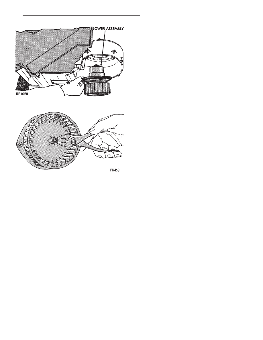
Fig. 5 Blower Motor and Wheel Assembly

Fig. 6 Blower Wheel Retaining Ring Removal and

Installation

Ä

HEATING AND AIR CONDITIONING

24 - 61

AA BODY PROCEDURE

WARNING: IF EQUIPPED WITH A/C, THE REFRIG-
ERATION SYSTEM MUST BE COMPLETELY EMPTY
BEFORE PROCEEDING WITH THIS OPERATION.

Refer to Group 8E and Group 23 for component re-

moval and installation when performing this opera-
tion.

(1) Perform steps 1 through 7 of Blower Motor re-

moval and installation.

(2) Remove relay panel above glove compartment

opening.

(3) Disconnect the A/C vacuum line connector and

radio noise capacitor connectors.

(4) Remove left windshield pillar trim cover.
(5) Remove left lower side cowl trim cover.
(6) Remove hood release handle mechanism attach-

ing screws.

(7) Remove steering column trim covers.
(8) Disconnect parking brake release mechanism

connecting rod. Gain access through fuse panel open-
ing.

(9) Remove lower left instrument panel silencer.
(10) Remove lower left instrument panel reinforce-

ment.

(11) Remove instrument panel center (radio) bezel.
(12) Remove forward floor console.
(13) Remove the radio.
(14) Remove the heater-A/C control.
(15) Remove cigar lighter.
(16) Remove

message

center/trip

computer,

if

equipped.

(17) Disconnect side window demister tubes from

top of heat A/C unit.

(18) Remove steering column upper attaching bolts

and allow the steering wheel to rest on the driver
seat cushion.

(19) Remove upper instrument panel (defroster

outlet) cover.

(20) Remove upper instrument panel attaching

screws from below the windshield opening.

(21) Loosen (do not remove) the left lower cowl in-

strument panel attaching screw.

(22) Remove the right lower cowl instrument panel

attaching screw.

CAUTION: Protect the passenger seat cover from
soiling or damage using a suitable cover.

(23) Carefully pull the right side of the instrument

panel away from the vehicle. Allow the instrument
panel to rest on the passenger seat cushion.

CAUTION: Before proceeding with the next opera-
tion, review the Safety Precautions and Warnings at
the front of this Group.

(24) From the engine compartment, drain the cool-

ing system and disconnect the heater hoses from the
heater core nipples. Plug the nipples to avoid spilling
coolant inside the vehicle.

(25) Disconnect the refrigerant lines from the ex-

pansion-valve at the dash panel on the right side of
the vehicle. Seal the refrigerant lines to prevent con-
tamination.

(26) Remove the expansion valve from the evapo-

rator plate. Seal the valve to avoid contamination.

(27) Remove the condensate drain tube.
(28) Remove heater-A/C unit to dash panel attach-

ing nuts.

(29) From inside the vehicle, pull rearward on the

heater-A/C unit to clear the dash panel silencer and
remove the unit from the vehicle.

To install, reverse the preceding operation. Refill

cooling system and test for leaks. Evacuate and
charge the refrigerant system and test overall perfor-
mance.

AG, AJ BODY PROCEDURE

WARNING: IF EQUIPPED WITH A/C, THE REFRIG-
ERATION SYSTEM MUST BE COMPLETELY EMPTY
BEFORE PROCEEDING WITH THIS OPERATION.

(1) Disconnect the battery negative cable.
(2) Drain the coolant from cooling system. Refer to

Group 7, Cooling System.

(3) Remove the air conditioner expansion valve (if

equipped).

(4) Disconnect the heater hoses from heater core.

Then plug or cap the tubes on heater core. This will
prevent spilling coolant into the interior of vehicle
during unit removal.

(5) Remove the condensate drain tube.
(6) Disconnect the A/C-heater vacuum supply line

from vacuum supply nipple (in the engine compart-
ment).

(7) Remove the four A/C-heater assembly-to-dash

panel attaching nuts.

(8) Remove the passenger side front seat. Refer to

Group 23, Body.

(9) Remove the kick panel/sill cover at right door

opening.

(10) Remove the body computer (Fig. 6) located at

the lower right section of the right front door pillar.

(11) Remove the glove box assembly. Refer to

Group 8E, Instrument Panel.

(12) Remove the carpeted panels from both sides of

the console.

(13) Un-clip the radio antenna cable from the

metal support (Fig. 6) located behind and below the
glove box opening.

(14) Instrument panel removal is not necessary to

remove the A/C-heater assembly from the vehicle.

24 - 62

HEATING AND AIR CONDITIONING

Ä

Although, part of the lower instrument panel must
be cut. The cut line is marked: CUT HERE FOR
A/C HTR REMOVAL.

This cut line is stamped (indented) into the right-

outer side of the instrument panel padding (outboard
of the glove box opening). Using a hacksaw blade,
cut the instrument panel padding along the indented
line from point A to point B (Fig. 7). CUT THE
PLASTIC ONLY
. Do not cut the metal support be-
hind the instrument panel padding.

(15) Remove the metal support behind and below

the glove box opening, and the previously cut piece of
the instrument panel that is riveted to it.

(16) Remove the radio choke, security alarm mod-

ule and the lamp outage module from above the
glove box opening (if equipped).

(17) Remove the plastic cover under the steering

column.

(18) Remove the metal support under the steering

column.

(19) AJ Body only: Remove the under-panel si-

lencer pad from under the glove box opening.

(20) Remove the lower heat distribution duct (3

screws).

(21) Remove the air distribution duct through the

opening at the left side of instrument panel.

(22) Reach through glove box opening and discon-

nect the demister hoses from the top of the A/C-heat-
er assembly.

(23) Disconnect the temperature control cable from

the bottom of the A/C-heater assembly and position
out of the way.

(24) Disconnect wiring at the blower motor and

fin-sensing cycling clutch switch electrical connectors.

(25) Un-plug the antenna cable from the radio.
(26) Remove the metal (A/C-heater-to-instrument

panel) hanger strap from the upper part of the A/C-
heater assembly.

(27) Roll back the floor carpeting from under the

A/C-heater assembly far enough to avoid restricting
unit removal.

(28) Remove the A/C-heater assembly through the

opening on the right side of the console, and remove
unit from vehicle.

The instrument panel (to the left side of the glove box

opening) must be slightly folded back to remove the
unit from the vehicle. If wrinkles appear in the instru-
ment panel after the unit has been installed, they may
be removed using a heat gun. Refer to Installation AG,
AJ Body for instructions.

To install, reverse steps (28) through (13). If wrinkles

have appeared in the instrument panel, apply low heat
from a heat gun over the wrinkled area. Do not
overheat the instrument panel padding or the
surrounding area.

Reverse steps (12) through (1). If equipped with A/C,

evacuate and charge the refrigerant system.

HEATER-A/C UNIT RECONDITION

The following operation requires the removal of the

heater-A/C unit assembly from the vehicle. Refer to
Heater-A/C Unit Assembly removal and installation in
this Group.

DISASSEMBLE

(1) Place the heater-A/C unit on a suitable work

surface. (Fig. 1).

(2) Locate and remove one retaining nut from the

blend-air door pivot shaft.

Fig. 7 Cut Line For A/C-heater Removal—AG/AJ

Body

Fig. 1 Position Heater-A/C Unit for Disassembly and

Reassembly

Ä

HEATING AND AIR CONDITIONING

24 - 63

(3) To remove the top cover from the A/C-heater

case, the crank arm must be removed (Fig. 2).

(4) Disconnect the vacuum lines from the defroster

and panel mode vacuum actuators and position them
out of the way.

(5) Remove three heater-A/C unit cover attaching

screws going upward at the defroster outlet chamber.

(6) Remove two heater-A/C unit cover attaching

screws going upward at the air inlet plenum.

(7) Remove eleven heater-A/C unit cover attaching

screws going downward into the housing. Then lift
the cover from the heater-A/C unit. (Fig. 3).

To reassemble, lower the heater-A/C unit cover

into place. Then guide the panel air mode door pivot
shaft into its socket and reverse the preceding oper-
ation.

BLEND-AIR DOOR

REMOVAL AND INSTALLATION

The following operation requires the removal of the

heater-A/C unit assembly from the vehicle. Refer to
Heater-A/C Unit Assembly removal and installation
in this Group.

(1) Remove Heater-A/C unit top cover.
(2) Remove the nut from bottom of the blend-air

door pivot shaft and lift the blend-air door from the
heater-A/C unit housing. (Fig. 4).

To install, reverse the preceding operation.

HEATER CORE

REMOVAL AND INSTALLATION

Refer to Heater A/C Unit Recondition in this

Group.

EVAPORATOR COIL

REMOVAL AND INSTALLATION

Refer to Heater A/C Unit Recondition in this

Group.

CONDENSATE DRAIN TUBE

Condensation that accumulates on the bottom of

the evaporator housing is drained from a rubber tube
through the dash panel and on to the ground. This
tube must be kept open to prevent condensate water
from collecting in the bottom of the heater A/C unit
housing.

The tapered end of the drain tube is designed to

keep contaminants from entering the heater A/C unit
housing. If the tube is pinched or blocked, condensate
cannot drain, causing water to back up and spill into

Fig. 2 Blend-Air Door Crank Linkage Removal

Fig. 3 Heater-A/C Unit Cover Removal and

Installation

Fig. 4 Blend-Air Door Removal and Installation

24 - 64

HEATING AND AIR CONDITIONING

Ä


Content   ..  198  199  200  201   ..