Chrysler Le Baron, Dodge Dynasty, Plymouth Acclaim. Manual - part 199
INSTALLATION
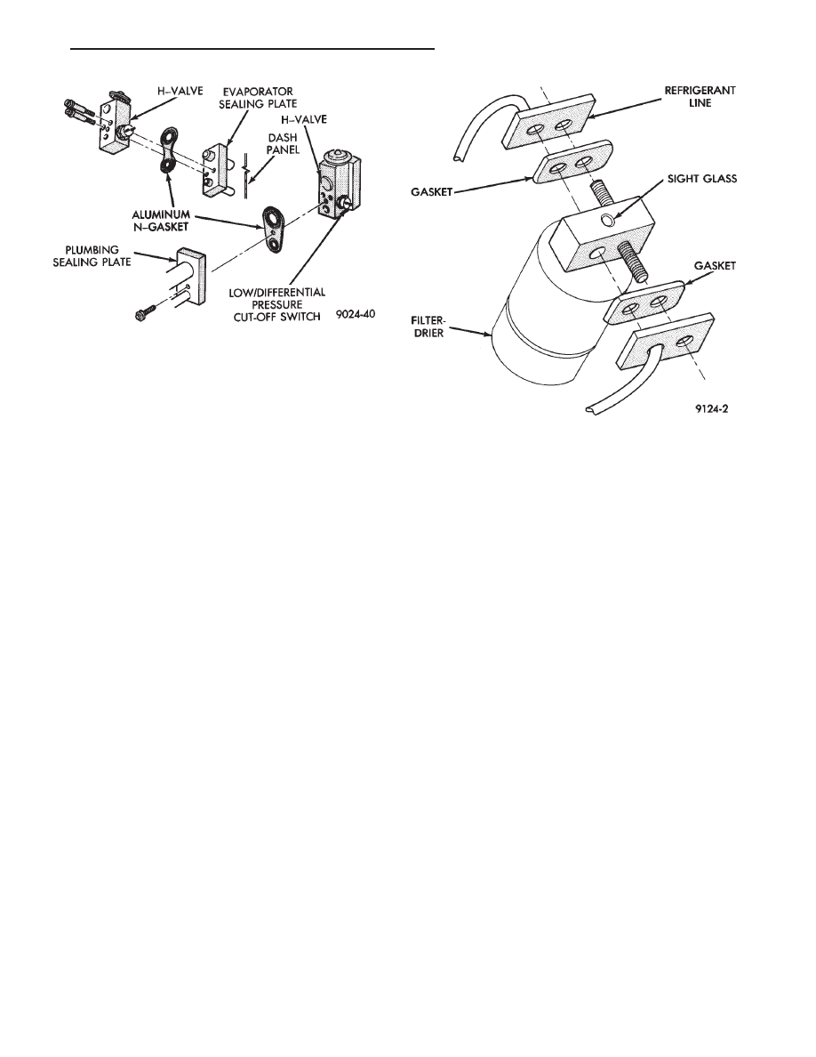
(1) Remove and replace the aluminum gasket on
the evaporator sealing plate.
(2) Carefully hold the expansion valve to the evap-
orator sealing plate (do not scratch sealing surface).
Install two attaching screws and tighten to 11
6 3
N
Im (100 6 30 inch lbs.).
(3) Remove and replace the aluminum gasket (Fig.
15) on the refrigerant line-sealing plate assembly.
(4) Carefully hold the refrigerant line-sealing plate
assembly to the expansion valve, install bolt and
tighten to 23
6 3 NIm (200 6 30 inch lbs.).
(5) Connect wires to low pressure cut-off switch.
(6) Evacuate and recharge system.
(7) After expansion valve is installed, system is
charged, and leaks have been checked, repeat A/C
performance check.
FILTER-DRIER ASSEMBLY
REMOVAL AND INSTALLATION
WARNING: THE REFRIGERATION SYSTEM MUST
BE COMPLETELY EMPTY BEFORE PROCEEDING
WITH THIS OPERATION.
(1) Remove the two high pressure lines from the
sides of the filter-drier assembly (Fig. 1). Then care-
fully separate the lines from filter-drier. Discard old
gaskets.
(2) Cover the open ends of the A/C lines to mini-
mize system contamination.
(3) Remove two mounting strap bolts and lift the
filter-drier from vehicle. If replacing the filter-drier
assembly, transfer the mounting strap to replace-
ment part.
To install, replace both refrigerant line to filter-
drier gaskets, and reverse the preceding operation.
Evacuate and recharge system.
CONDENSER ASSEMBLY
The A/C condenser is mounted to the radiator with
bolts (upper) and mounting pads (lower).
WARNING: THE REFRIGERATION SYSTEM MUST BE
COMPLETELY REMOVED BEFORE PROCEEDING
WITH THIS OPERATION. REFER TO DISCHARGING
REFRIGERATION SYSTEM IN THIS GROUP.
REMOVAL AND INSTALLATION
(1) Using a refrigerant recovery machine, remove
the refrigerant from the A/C system.
(2) Remove the refrigerant line mounting nut (Fig.
2) and separate the refrigerant lines from condenser
sealing plate.
(3) Cover the open ends of the A/C lines and con-
denser to minimize system contamination.
(4) Remove the coolant overflow bottle, electric cool-
ing fans and radiator assembly. Also remove the turbo-
charger inter-cooler if equipped. Refer to Group 7,
Cooling System.
On some models, complete removal of the ra-
diator, or coolant drainage is not necessary. The
radiator may be moved slightly rearward to re-
move the condenser.
(5) Remove the two bolts securing the condenser
assembly to the radiator.
(6) Slip the condenser from the lower radiator
mounting brackets.
(7) Remove condenser.
To install, replace all O-rings and gaskets and coat
sealing surfaces with approved refrigerant oil. Then
reverse the preceding operation. When installing a
Fig. 27 Expansion Valve
Fig. 1 Filter-Drier—Typical
Ä
HEATING AND AIR CONDITIONING
24 - 57