Chrysler Le Baron, Dodge Dynasty, Plymouth Acclaim. Manual - part 198


  Index      Chrysler     Chrysler Le Baron, Dodge Dynasty, Plymouth Acclaim - service repair manual 1993 year


Search            


Content   ..  196  197  198  199   ..


Chrysler Le Baron, Dodge Dynasty, Plymouth Acclaim. Manual - part 198


FIN-SENSING CYCLING CLUTCH SWITCH

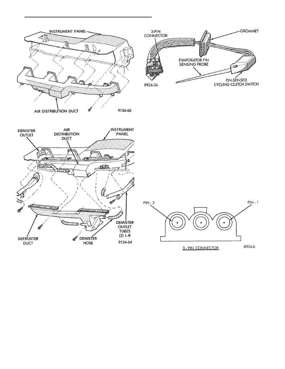
The Fin-Sensing Cycling Clutch Switch (FCCS)

(Fig. 17) is located in the heater-A/C unit housing
near the blower motor and placed in the evaporator
fins. The FCCS prevents evaporator condensate
freeze-up. This is done by cycling the compressor
clutch OFF when evaporator temperature drops be-
low freeze point. It cycles ON when the evaporator
temperature rises above freeze point. The FCCS uses
a thermistor probe in a capillary tube inserted be-
tween the evaporator fins in the heater-A/C unit
housing. If the compressor clutch does not cycle, and
all other clutch circuit components test correct, test
the switch.

At temperatures above 32°C (90°F) the compressor

clutch may engage continuously and not cycle. This
is due to evaporator temperature above the freezing
point.

DIAGNOSIS

The work area and vehicle must be between 21°C

(70°F) and 32°C (90°F) when testing the Fin-sensing
Cycling Switch.

(1) Disconnect the 3-wire connector from switch

lead located behind the glove box.

(2) Test for voltage between pin #1 to pin #3 on

the wire harness connector (Fig. 18). If voltage is not
detected, refer to the Front Wheel Drive Car-Wiring
Diagrams Service Manual. If voltage is detected,
jump pin #1 to pin #3 using a jumper wire. Com-
pressor clutch should engage.

(3) If compressor clutch engages, test for continuity

from terminal pin #1 to pin #3 of the switch lead
connector. Continuity should be detected. If not, re-
place the Fin-sensing Cycling Clutch Switch.

REMOVAL AND INSTALLATION

(1) Remove the cover/housing from the heater-A/C

blower motor. Refer to Blower Motor removal and in-
stallation. Remove the cover only. Blower motor or
blower motor wheel removal is not necessary.

(2) Disconnect the (three pin) wiring pigtail con-

nector from the clutch switch sensor harness (located
on the outside of the A/C-heater housing). Push the
wire harness grommet (attached to the A/C-heater

Fig. 15 Air Distribution Duct

Fig. 16 Defroster Ducts/Demister Ducts and Hoses

Fig. 17 Fin-sensing Cycling Clutch Switch

Fig. 18 Fin-sensing Cycling Clutch Switch Harness

Connector

Ä

HEATING AND AIR CONDITIONING

24 - 53

housing) through the hole in the housing. Feed the
wire harness and connector through the opening and
into the housing (Fig. 19).

(3) Work through the air inlet opening (to the left of

the blower motor wheel). Pull the fin-sensing cycling
switch from the A/C evaporator (Fig. 20). The metal
probe on the switch is pushed into the evapora-
tor approximately three inches.

To install, reverse the preceding operation. The

switch probe should not be installed in the original
location (hole). Insert the probe in the evaporator coil
approximately 5 mm (3 to 4 fins) to the right or left of
the position it was removed. This will insure correct
temperature sensing and system performance. Exces-
sive force should not be required for probe insertion.
Care should be taken not to damage the A/C evaporator
coil or the switch probe.

LOW OR DIFFERENTIAL PRESSURE CUT-OFF
SWITCH

The Low Pressure Cut-Off (LPCO) Switch (Fig. 21)

monitors the refrigerant gas pressure on the suction

side of the system. The LPCO is located on the ex-
pansion valve, and the expansion valve is silver in
color when a fixed displacement compressor is used.
The LPCO turns off voltage to the compressor clutch
coil when refrigerant gas pressure drops to levels
that could damage the compressor. The LPCO is a
sealed factory calibrated unit. It must be replaced if
defective.

LPCO SWITCH DIAGNOSIS

The work area must not be below 10°C (50°F) to

test the compressor clutch circuit.

(1) With gear selector in park or neutral and park

brake set, start engine and allow to idle.

(2) Raise hood and disconnect LPCO switch con-

nector boot.

(3) Using a suitable jumper wire, jump across the

terminals inside wire connector boot.

(4) If the compressor clutch does not engage, the

cycling clutch switch, wiring, relay, or fuse can be
defective. Refer to Group 8W, Wiring Diagrams.

(5) If clutch engages, connect manifold gauge set.

Read low pressure gauge. At pressure above 97 kPa
(14 psi) and above, LPCO switch will complete the
clutch circuit. If the low pressure gauge reads below
172 kPa (25 psi), the system is low on refrigerant
charge or empty due to a leak. Refer to Testing For
Refrigerant Leaks in the Refrigerant Service Proce-
dures section.

(6) Install connector boot on switch and repeat step

number 3. If the clutch does not engage, replace the
LPCO switch.

REMOVAL AND INSTALLATION

WARNING: THE REFRIGERATION SYSTEM MUST
BE COMPLETELY EMPTY BEFORE PROCEEDING
WITH THIS OPERATION. REFER TO REFRIGERANT
RECOVERY SECTION.

Fig. 21 Low Pressure Cut-Off Switch

Fig. 19 Remove or Install Wire Harness Grommet

Fig. 20 Remove or Install Fin-sensing Cycling

Clutch Switch

24 - 54

HEATING AND AIR CONDITIONING

Ä

(1) Disconnect the boot like wire connector at the

cut-off switch.

(2) Using a sender unit type socket, remove the

switch from the expansion valve (Fig. 22 or 23).

To install, assure an adequate seal by using a small

amount of thread sealing tape on the replacement
switch and reverse the preceding steps.

Evacuate and charge the system.

EXPANSION VALVE

DIAGNOSIS

BLACK EXPANSION VALVE TEST

Liquid CO

2

is required to test the expansion

valve. It is available from most welding supply
facilities. CO

2

is also available from companies

which service and sell fire extinguishers.

Review Safety Precautions and Warnings before pro-

ceeding with this operation. The work area must

be 21°C to 27°C (70°F to 85°F) when testing expansion
valve. To test the expansion valve:

(1) Connect a charging station or manifold gauge set

to the refrigerant system service ports.

(2) Verify the refrigerant charge level using the sight

glass method.

(3) Disconnect the wire connector at the differential

pressure cut-off switch. Using a jumper wire, jump
across the terminals inside the connector boot (Fig. 24).

(4) Close all doors, windows and vents to the passen-

ger compartment.

(5) Set heater-A/C control to A/C, full heat, FLOOR,

and high blower.

(6) Start the engine and hold the idle speed (1000

rpm). After the engine has reached running tempera-
ture, allow the passenger compartment to heat up.
This will create the need for maximum refrigerant flow
into the evaporator.

(7) Discharge (high pressure) gauge should read 965

to 1655 kPa (140 to 240 psi) when the refrigerant
charge is sufficient. If system cannot achieve proper
pressure, replace the expansion valve. If pressure is
correct, record reading and proceed with test.

WARNING: PROTECT SKIN AND EYES FROM CON-
TACTING CO

2

PERSONAL INJURY CAN RESULT.

(8) If discharge pressure is within specified range,

freeze the expansion valve control head (Fig. 8) for
30 seconds. Use a super cold substance (liquid
CO

2

).Do not spray R-12 Refrigerant on the expan-

sion valve for this test. Refer to Refrigerant
Recycling in the Refrigerant Service Procedures
section. 
If compressor discharge (high) pressure does
not drop by 15% or more than the pressure recorded in
step 7, replace the expansion valve. Allow the expan-
sion valve to thaw. The discharge pressure should

Fig. 22 Low Pressure Cut-Off Switch and Expansion

Valve—Typical

Fig. 23 Differential Pressure Cut-Off Switch and Ex-

pansion Valve—Typical

Fig. 24 Differential Pressure Cut-Out Switch

Ä

HEATING AND AIR CONDITIONING

24 - 55

stabilize to the pressure recorded in step 7. If the
pressure does not stabilize, replace the expansion
valve.

When expansion valve tests are complete, refer to

Heater and A/C Performance Tests and remove all test
equipment before returning vehicle to use.

SILVER EXPANSION VALVE TEST

Expansion valve tests should be performed af-

ter compressor tests.

Liquid CO

2

is required to test the expansion

valve. It is available from most welding supply
facilities. CO

2

is also available from companies

which service and sell fire extinguishers.

Review Safety Precautions and Warnings in the

General Information section of this Group. The work
area and vehicle must be 21°C to 27°C (70°F to 85°F)
when testing expansion valve. To test the expansion
valve:

(1) Connect a charging station or manifold gauge set

to the refrigerant system service ports.

(2) Verify the refrigerant charge level using the sight

glass method.

(3) Disconnect wire connector at low pressure cut-off

switch (Fig. 25). Using a jumper wire, jump terminals
inside wire connector boot.

(4) Close all doors, windows and vents to the passen-

ger compartment.

(5) Set heater-A/C control to A/C, full heat, FLOOR,

and high blower.

(6) Start the engine and hold the idle speed (1000

rpm). After the engine has reached running tempera-
ture, allow the passenger compartment to heat up.
This will create the need for maximum refrigerant flow
into the evaporator.

(7) If the refrigerant charge is sufficient, discharge

(high pressure) gauge should read 965 to 1655 kPa (140
to 240 psi). Suction (low pressure) gauge should read
140 kPa to 207 kpa (20 psi to 30 psi). If system

cannot achieve proper pressure readings, replace the
expansion valve. If pressure is correct, proceed with
test.

WARNING: PROTECT SKIN AND EYES FROM CON-
TACTING CO

2

PERSONAL INJURY CAN RESULT.

(8) If suction side low pressure is within specified

range, freeze the expansion valve control head (Fig. 26)
for 30 seconds. Use a super cold substance (liquid CO

2

).

Do not spray R-12 Refrigerant on the expansion
valve for this test. 
Suction side low pressure should
drop to -50 kPa (-15 in. Hg) If not, replace expansion
valve.

(9) Allow expansion valve to thaw. The low pressure

gauge reading should stabilize at 140 kPa to 240 kPa
(20 psi to 30 psi). If not, replace expansion valve.

When expansion valve test is complete, test A/C

overall performance. Refer to the Heater and A/C
Performance Test in this section. Remove all test
equipment before returning vehicle to use.

REMOVAL

WARNING: THE REFRIGERATION SYSTEM MUST BE
COMPLETELY EMPTY BEFORE PROCEEDING WITH
THIS OPERATION.

(1) Remove the boot-type wire connector from the

pressure cut-off switch.

(2) Remove the attaching bolt in center of refriger-

ant line-plumbing sealing plate (Fig. 27).

(3) Carefully pull the refrigerant line-sealing plate

assembly from the expansion valve towards front of
vehicle. Do Not scratch the expansion valve sealing
surfaces with pilot tubes.

(4) Cover the openings on A/C line-sealing plate

assembly to prevent contamination.

(5) Remove two screws securing the expansion valve

to the evaporator sealing plate.

(6) Carefully remove valve.

Fig. 25 Low Pressure Cut-Off Switch

Fig. 26 Expansion Valve

24 - 56

HEATING AND AIR CONDITIONING

Ä


Content   ..  196  197  198  199   ..