Chrysler Le Baron, Dodge Dynasty, Plymouth Acclaim. Manual - part 196


  Index      Chrysler     Chrysler Le Baron, Dodge Dynasty, Plymouth Acclaim - service repair manual 1993 year


Search            


Content   ..  194  195  196  197   ..


Chrysler Le Baron, Dodge Dynasty, Plymouth Acclaim. Manual - part 196


(3) Visually inspect all parts for damage.
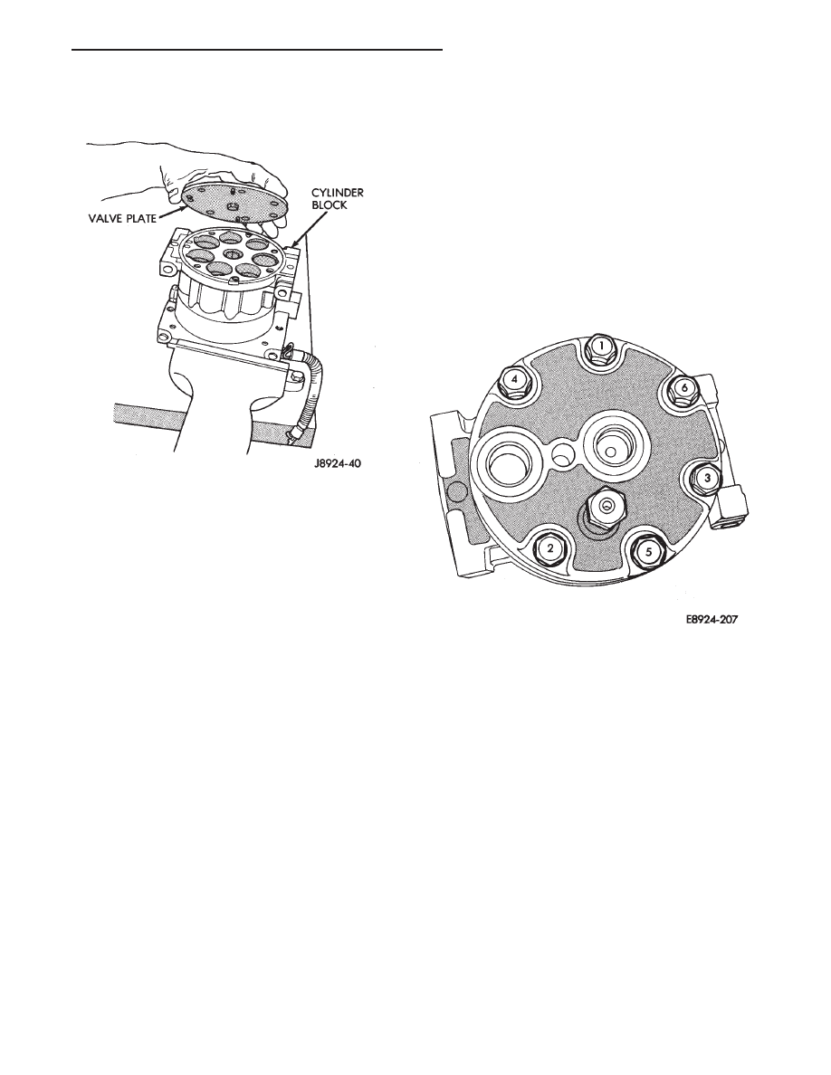
(4) Separate the valve plate from the cylinder

block (Fig. 2).

INSPECTION

Visually inspect the rear valves and discharge re-

tainer for damage. Discard any component if any por-
tion is damaged.

CLEANING

If valve plate and/or cylinder head are to be reused,

carefully remove gasket materials using the gasket
scraper. Do not damage cylinder block or valve plate
surfaces.

INSTALLATION

When installing the cylinder head valve plate,

use the new gaskets in the parts kit.

(1) Coat new valve plate gasket with clean refriger-

ant oil.

(2) Install valve plate gasket by aligning valve plate

gasket to locating pin holes and oil orifice in cylinder
block. (For easy reference, the gaskets have a notch at
the bottom outside edge).

(3) Install valve plate by aligning valve plate locat-

ing pins to the pin holes in the block and position valve
plate.

(4) Install cylinder head and tighten bolts in order to

32 N

Im (24 ft. lbs.) torque (Fig. 3).

REFRIGERANT SYSTEM DIAGNOSIS

Refer to the Refrigerant System Diagnosis chart in

this section.

Fig. 2 Valve Plate Removal

Fig. 3 Cylinder Head Bolt Torque Sequence

Ä

HEATING AND AIR CONDITIONING

24 - 45

REFRIGERANT SYSTEM DIAGNOSIS

24 - 46

HEATING AND AIR CONDITIONING

Ä

COMPONENT SERVICE PROCEDURES

INDEX

page

page

Air Distribution Duct

. . . . . . . . . . . . . . . . . . . . . . 50

Air Distribution Duct

. . . . . . . . . . . . . . . . . . . . . . 52

Ambient Switch

. . . . . . . . . . . . . . . . . . . . . . . . . . 47

Blend-Air Door

. . . . . . . . . . . . . . . . . . . . . . . . . . 64

Blower Motor

. . . . . . . . . . . . . . . . . . . . . . . . . . . . 58

Blower Motor Wheel Assembly

. . . . . . . . . . . . . . 58

Blower Resistor Block

. . . . . . . . . . . . . . . . . . . . . 49

Condensate Drain Tube

. . . . . . . . . . . . . . . . . . . 64

Condenser Assembly

. . . . . . . . . . . . . . . . . . . . . . 57

Condenser Fan Control Switch

. . . . . . . . . . . . . . 47

Defroster Duct

. . . . . . . . . . . . . . . . . . . . . . . . . . . 51

Defroster Duct Adapter

. . . . . . . . . . . . . . . . . . . . 51

Defroster Ducts/Demister Ducts and Hoses

. . . . . 52

Differential Pressure Cut-Out Switch Diagnosis

. . 48

Evaporator Coil

. . . . . . . . . . . . . . . . . . . . . . . . . . 64

Expansion Valve

. . . . . . . . . . . . . . . . . . . . . . . . . 55

Filter-Drier Assembly

. . . . . . . . . . . . . . . . . . . . . . 57

Fin-Sensing Cycling Clutch Switch

. . . . . . . . . . . . 53

Heater Core

. . . . . . . . . . . . . . . . . . . . . . . . . . . . 64

Heater Hoses

. . . . . . . . . . . . . . . . . . . . . . . . . . . 51

Heater-A/C Unit Assembly—Removal and

Installation

. . . . . . . . . . . . . . . . . . . . . . . . . . . . 61

Heater-A/C Unit Recondition

. . . . . . . . . . . . . . . . 63

Low or Differential Pressure Cut-Off Switch

. . . . . 54

Temperature Control Cable—AA,AP,AG and

AJ Models

. . . . . . . . . . . . . . . . . . . . . . . . . . . . 49

Temperature Control Cable—AC/AY Models

. . . . 48

Vacuum Actuator—Fresh/Recirc Door

. . . . . . . . . 50

Vacuum Actuators—Mode Doors

. . . . . . . . . . . . . 52

AMBIENT SWITCH

The ambient switch is a temperature sensor located

in front of the condenser behind the grille (Fig. 1).
The ambient switch prevents the compressor from
engaging in cold temperatures. The ambient switch
is a sealed factory calibrated unit. It must be re-
placed if defective.

AMBIENT SWITCH TEST

(1) Disconnect ambient switch wire connector.
(2) Using a suitable ohm meter or continuity

tester, test for continuity across the ambient switch
terminals.

(a) At temperature above 10°C (50°F), the switch

circuit should be complete.

(b) Chill the switch with ice to below 10°C (50°F)

and test for continuity. The switch circuit should
be open, with continuity not detected.
Replace ambient switch if defective.

REMOVAL AND INSTALLATION

(1) Remove the one attaching screw.
(2) Remove the sensor/bracket assembly from the

vehicle.

To install, reverse the preceding operation.

CONDENSER FAN CONTROL SWITCH

The Fan Control Switch is located on the plumbing

discharge line at the A/C compressor (Fig. 2). The fan
control switch cycles the radiator/condenser fan on and
off by monitoring the compressor discharge pressure.
The radiator top tank temperature sensor can over ride
the function of the fan control switch. It can cycle the
radiator/condenser fan on and off depending on the
engine temperature.

FAN CONTROL SWITCH DIAGNOSIS

Review Safety Precautions and Warnings before pro-

ceeding. Connect a manifold gauge set to the refriger-
ant system service ports. Work area temperature can
not be below 21°C (70°F).

Fig. 1 Ambient Temperature Sensor Switch—Typical

Mounting

Fig. 2 Condenser Fan Control Switch

Ä

HEATING AND AIR CONDITIONING

24 - 47

WARNING:

AVOID

RADIATOR/CONDENSER

FAN

BLADES

WHEN

WORKING

IN

THE

RADIATOR

AREA. FAN IS CONTROLLED BY TEMPERATURE
AND CAN START ANY TIME IGNITION IS ON. PER-
SONAL INJURY CAN RESULT.

(1) Disconnect fan control switch wire connector.
(2) Using a suitable jumper wire, jump across ter-

minals in wire connector.

(3) Connect a suitable continuity tester across fan

control switch terminals.

(4) Start engine and set idle at 1300 rpm. The ra-

diator fan should run constantly.

(5) Set the A/C controls to A/C and high blower.
(6) If the high pressure gauge reads below 1102

kPa (160 psi) there should be no continuity across
the switch terminals.

CAUTION: Do not allow engine to overheat when ra-
diator air flow is blocked.

(7) Block radiator air flow with a suitable cover to

increase the high side pressure to at least 1585 kPa
(230 psi). Electrical continuity should be detected
across the fan control switch terminals.

(8) Remove cover from front of vehicle to allow

high side pressure to decrease. When pressure drops
below 1102 kPa (160 psi), continuity should cease.

If fan control switch is defective, replace it.

REMOVAL AND INSTALLATION

CAUTION: Refrigerant removal is not necessary
when removing the Condenser Fan Control Switch.
However, a small amount of refrigerant will vent
from the switch port. Review the refrigerant han-
dling section of Safety Precautions and Warnings in
the General Information section of this Group.

(1) Disconnect wire connector from condenser fan

control switch.

(2) Loosen and quickly rotate the switch counter-

clockwise and separate from the high pressure line
switch port.

To install, reverse the preceding operation.

DIFFERENTIAL PRESSURE CUT-OUT SWITCH
DIAGNOSIS

The Differential Pressure Cut-Out (DPCO) Switch

(Fig. 3) monitors the liquid refrigerant pressure on
the liquid side of the system. The DPCO is located on
the expansion valve. The expansion valve is black in
color when a variable displacement compressor is
used. The DPCO turns off voltage to the compressor
clutch coil when liquid refrigerant pressure drops to
levels that could damage the compressor. The DPCO
is a sealed factory calibrated unit. It must be re-
placed if defective.

DPCO SWITCH DIAGNOSIS

The work area must not be below 10°C (50°F) to

test the compressor clutch circuit.

(1) With gear selector in park or neutral, and park

brake set, start engine and allow to idle.

(2) Raise hood and disconnect DPCO switch con-

nector boot.

(3) Using a suitable jumper wire, jump across the

terminals inside wire connector boot.

(4) If clutch does not engage, the wiring, fuse, re-

lay, ambient switch, or high pressure cut-off switch
can be defective. Refer to Group 8W, Wiring Dia-
grams.

(5) If clutch engages, connect a suitable manifold

gauge set. Read low pressure gauge. At pressure 283
kPa (41 psi) and above, DPCO switch will complete
the clutch circuit. If the low pressure gauge reads be-
low 317 kPa (46 psi), the system is low on refrigerant
charge or empty due to a leak. Refer to Testing For
Refrigerant Leaks in the Refrigerant Service Proce-
dures section.

(6) Install connector boot on switch and repeat step

number 3. If the clutch does not engage, replace the
DPCO switch.

TEMPERATURE CONTROL CABLE—AC/AY MODELS

REMOVAL AND INSTALLATION

A Temperature Control Cable is used on non-ATC

heat or heater-A/C systems only. ATC (Automatic
Temperature Control) systems use an electrically op-
erated temperature control. Refer to the ATC section
of this Group.

(1) Remove the A/C-Heater control panel assembly.

Refer to A/C-Heater Control Replacement in Group
8E Instrument Panel. Disconnect the cable attaching
flag from the A/C-heater control and remove the ca-
ble from control panel.

Fig. 3 Differential Pressure Cut-Out Switch

24 - 48

HEATING AND AIR CONDITIONING

Ä


Content   ..  194  195  196  197   ..