Chrysler Le Baron, Dodge Dynasty, Plymouth Acclaim. Manual - part 195


  Index      Chrysler     Chrysler Le Baron, Dodge Dynasty, Plymouth Acclaim - service repair manual 1993 year


Search            


Content   ..  193  194  195  196   ..


Chrysler Le Baron, Dodge Dynasty, Plymouth Acclaim. Manual - part 195


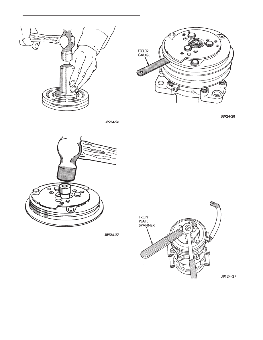
(11) Replace shaft hex nut. Tighten the hex nut to 37

N

Im (27 ft. lbs.) torque.

(12) Check air gap with feeler gauge (Fig. 12). The

specification is 0.406-0.787 mm (0.016-0.031 inch). If
air gap is not consistent around the circumference,
lightly pry up at the minimum variations. Lightly tap
down at points of maximum variation.

The air gap is determined by the spacer shims.

When installing the original or a new clutch
assembly, try the original shims first. When in-
stalling a new clutch onto a compressor that
previously did not have a clutch, use 0.040, 0.020,
and 0.005 shims from the clutch accessory sack.

(13) If the air gap does not meet the specification

given, add or subtract shims as required.

COMPRESSOR SHAFT SEAL

Using a refrigerant recovery machine, remove the

refrigerant from the A/C system before replacing
shaft seal.

REMOVAL

(1) Insert the 2 pins of the front plate spanner into

any 2 threaded holes of the clutch front plate (Fig.
1). Hold clutch plate stationary. Remove hex nut
with 19 mm (3/4 inch) socket.

(2) Remove clutch front plate using puller (Fig. 2).

Align puller center bolt to compressor shaft. Thumb
tighten the 3 puller bolts into the threaded holes.

(3) Turn center bolt clockwise with 19 mm (3/4

inch) socket until front plate is loosened.

Fig. 12 Check Air Gap

Fig. 1 Hex Nut Removal

Fig. 10 Tool Set Driver

Fig. 11 Front Plate Installation

Ä

HEATING AND AIR CONDITIONING

24 - 41

Shaft seal replacement should be done on the

bench. Never use any old parts of the shaft seal
assembly. Rebuild the complete assembly.

(4) Using either of the snap ring tools, insert the tool

points into the 2 holes of the felt ring metal retainer.
Lift the felt ring out (Fig. 3).

(5) Remove the clutch shim. Use O-ring hook and a

small screwdriver to prevent shim from binding on
shaft (Fig. 4).

(6) Remove shaft seal seat retaining snap ring with

pinch type snap ring pliers (Fig. 5).

(7) Remove the shaft seal seat, using seal seat tool

(Fig. 6).

(8) Insert the Seal Remover and Installer Tool

against the seal assembly. Press down against the
seal spring and twist the tool until it engages the
slots of the seal cage (Fig. 7). Lift out seal assembly.

INSTALLATION

(1) Clean seal cavity thoroughly with a lint-free or

synthetic cloth and clean refrigerant oil. Then blow
out with dry pressurized vapor.

(2) Make sure all foreign substances are thor-

oughly removed.

(3) Insert Seal Sleeve Protector over compressor

shaft (Fig. 8).

Fig. 4 Clutch Shim Removal

Fig. 5 Snap Ring Removal

Fig. 2 Remove Clutch Front Plate

Fig. 3 Felt Ring Removal

24 - 42

HEATING AND AIR CONDITIONING

Ä

(4) Do not touch the new seal lapping surfaces. Dip

the mating surfaces in clean refrigerant oil before
proceeding.

(5) Engage slots of Seal Remover and Installer to

new seal cage and insert seal assembly firmly into
place in the compressor seal cavity (Fig. 9). Twist
tool in opposite direction to disengage tool from seal
cage. Remove tool.

(6) Coat seal retainer with clean refrigerant oil.

Use seal seat tool to install (Fig. 10). Press lightly
against seal.

(7) Install snap ring. Beveled edge lies outward

from compressor. Flat side lies toward compressor. It
may be necessary to lightly tap the snap ring to se-
curely position it in its groove.

(8) Replace clutch spacer shims.
(9) Tap new felt ring into place (Fig. 11).
(10) Align front plate key-way to compressor shaft

key.

(11) Using shaft protector, tap front plate to shaft

until it has bottomed to the clutch shims. Listen for
a distinct change of sound during the tapping pro-
cess.

(12) Replace shaft hex nut. Tighten the hex nut to

37 N

Im (27 ft. lbs.) torque.

(13) Check air gap with feeler gauge (Fig. 12). The

specification is 0.406-0.787 mm (0.016-0.031 inch). If

Fig. 6 Shaft Seal Seat Removal

Fig. 7 Seal Assembly Removal

Fig. 8 Insert Seal Sleeve Protector

Fig. 9 Compressor Shaft Seal Installation

Ä

HEATING AND AIR CONDITIONING

24 - 43

air gap is not consistent around the circumference,
lightly pry up at the minimum variations. Lightly tap
down at points of maximum variation.

The air gap is determined by the spacer shims.

When installing the original or a new clutch
assembly, try the original shims first. When in-
stalling a new clutch onto a compressor that
previously did not have a clutch, use 0.040, 0.020,
and 0.005 shims from the clutch accessory sack.

(14) If the air gap does not meet the specification

given, add or subtract shims as required.

CYLINDER HEAD/VALVE PLATE

REMOVAL

(1) Remove cylinder head bolts.
(2) Using a small hammer and a gasket scraper

separate the cylinder head from the valve plate (Fig.
1).

Fig. 12 Check Air Gap

Fig. 1 Cylinder Head and Valve Plate

Fig. 10 Install Seal Retainer

Fig. 11 Install New Felt Ring

24 - 44

HEATING AND AIR CONDITIONING

Ä


Content   ..  193  194  195  196   ..