Chrysler Le Baron, Dodge Dynasty, Plymouth Acclaim. Manual - part 193
(4) Remove rotor-pulley retaining snap ring with
Snap Ring Pliers C-4574. Slide rotor-pulley assembly
from compressor. Use a plastic hammer, if necessary.
(5) Loosen the lead wire retaining clamps and re-
move lead wire from the compressor front end plate.
Disconnect the lead wire from the thermal limiter
switch.
(6) Remove the snap ring which secures the field
coil-core assembly to the front boss (Fig. 2). Note the
alignment of field coil-core assembly when removing.
WARNING: TAKE CARE THAT THE SNAP RING
DOES NOT FLY OUT FROM THE GROOVE.
INSPECTION
Examine frictional faces of the rotor-pulley and ar-
mature plate for wear. The pulley and plate should
be replaced if there is excessive wear or scoring. If
the friction surfaces are oily, inspect the shaft nose
area of the compressor for excess oil. If excess oil is
present, the shaft seal is leaking and will have to be
replaced.
Check rotor-pulley bearing for roughness or exces-
sive grease leakage. Check for bearing grease con-
tamination on armature plate faces.
The rotor-pulley and armature plate should be re-
placed as a matched set.
INSTALLATION
(1) Position the back of the field coil-core over the
compressor front boss. This will allow the locating
nipple on the back of the coil to line up with the lo-
cating indentation on the front boss. This ensures
correct angular position of the clutch coil and lead
wire.
(2) Fasten lead wire to the compressor front plate
with the retaining clip. Connect the lead wire to the
thermal limiter switch.
(3) Install field coil-core retaining snap ring (bevel
side outward) with Snap Ring Pliers C-4574. Press
snap ring to make sure it is properly seated in the
groove.
CAUTION: If snap rings on field coil-core and rotor-
pulley are not fully seated, they will vibrate out. A
clutch failure and possible severe damage to the
compressor could result.
(4) Slide pulley assembly onto compressor.
CAUTION: Do not mar the pulley frictional surface.
(5) Install rotor-pulley assembly retaining snap
ring (bevel side outward) with Snap Ring Pliers
C-4574. Press the snap ring to make sure it is prop-
erly seated in the groove.
(6) If the original armature plate assembly and ro-
tor-pulley assembly are to be reused, the old shim(s)
can be used. If not, place a trial stack of shims, 2.54
mm (0.10 in.) thick, on the compressor shaft against
the shoulder of the armature plate.
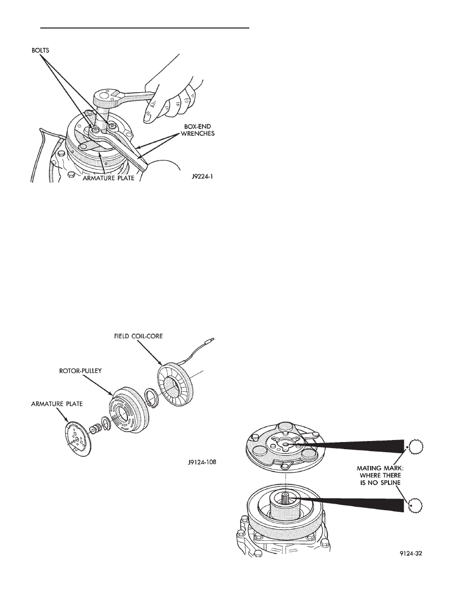
(7) Install armature plate to the compressor shaft.
Note the machined mating splines (Fig. 3).
Fig. 1 Compressor Shaft Nut Removal/Installation
Fig. 2 Armature Plate/Rotor-Pulley/Field Coil-Core
Fig. 3 Aligning Clutch Plate Splines
Ä
HEATING AND AIR CONDITIONING
24 - 33