Chrysler Le Baron, Dodge Dynasty, Plymouth Acclaim. Manual - part 191


  Index      Chrysler     Chrysler Le Baron, Dodge Dynasty, Plymouth Acclaim - service repair manual 1993 year


Search            


Content   ..  189  190  191  192   ..


Chrysler Le Baron, Dodge Dynasty, Plymouth Acclaim. Manual - part 191


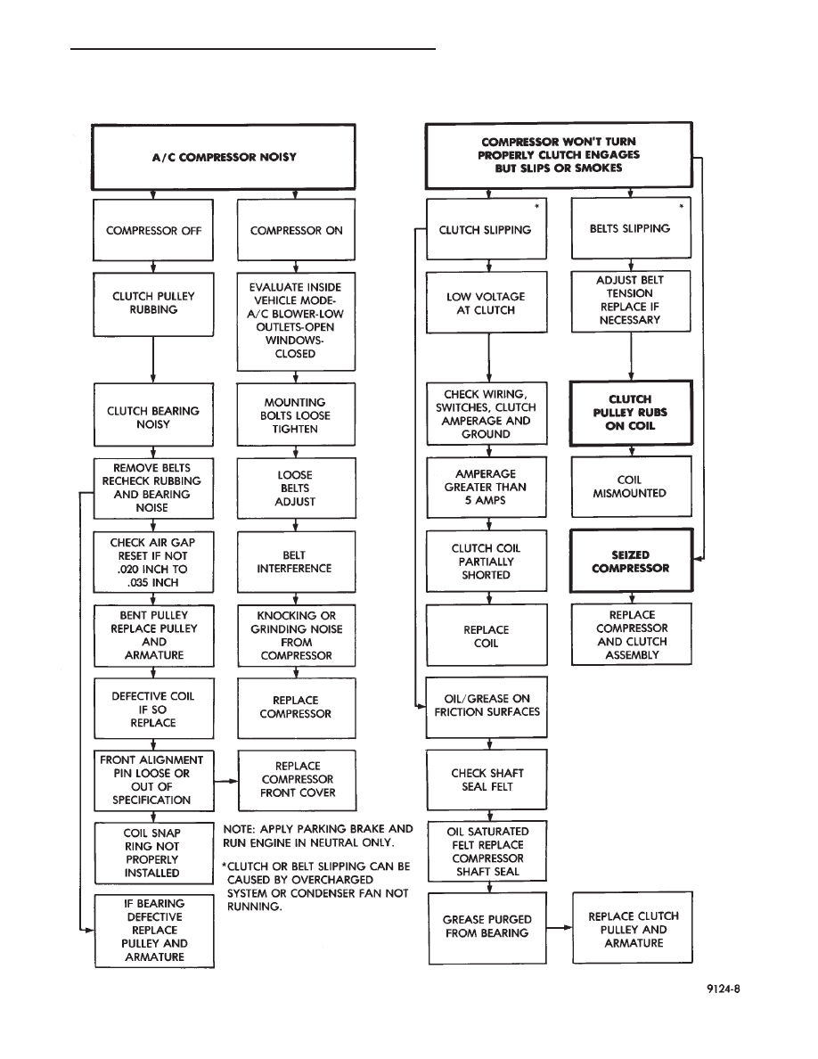
COMPRESSOR NOISE AND COMPRESSOR CLUTCH DIAGNOSIS

Ä

HEATING AND AIR CONDITIONING

24 - 25

REMOVAL

Compressor assembly must be removed from mount-

ing. Although, refrigerant removal is not necessary.

(1) Remove the compressor shaft bolt (Fig. 1). A

band type oil filter removal tool can be placed around
the clutch plate to aid in bolt removal.

(2) Tap the clutch plate with a plastic hammer and

remove clutch plate and shim (Fig. 2).

CAUTION: Do not use screwdrivers between the
clutch plate assembly and pulley to remove front
plate as this may damage the front plate assembly.

(3) Remove pulley retaining snap ring with Snap

Ring Pliers (C-4574), and slide pulley assembly off of
compressor (Fig. 3).

(4) Remove coil wire clip screw and wire harness.

(5) Remove snap ring retaining field coil onto com-

pressor housing (Fig. 4). Slide field coil off of com-
pressor housing.

(6) Examine frictional faces of the clutch pulley

and front plate for wear. The pulley and front plate
should be replaced if there is excessive wear or scor-
ing. If the friction surfaces are oily, inspect the shaft
nose area of the compressor for oil and remove the
felt from the front cover. If the compressor felt is sat-
urated with oil, the shaft seal is leaking and will
have to be replaced.

Fig. 1 Compressor Shaft Bolt and Clutch Plate

Fig. 2 Clutch Plate and Shim(s)

Fig. 3 Removing Pulley Snap Ring

Fig. 4 Clutch Coil Snap Ring

24 - 26

HEATING AND AIR CONDITIONING

Ä

(7) Check bearing for roughness or excessive leak-

age of grease. Replace bearing as required.

INSTALLATION

(1) Align pin in back of field coil with hole in com-

pressor end housing, and position field coil into place.
Make sure that lead wires are properly routed, and
fasten with the wire clip retaining screw.

(2) Install field coil retaining snap ring with Snap

Ring Pliers (C-4574). The bevel side of the snap ring
must be outward. Also both eyelets must be to the
right or left of the pin on the compressor. Press snap
ring to make sure it is properly seated in the groove.

CAUTION: If snap ring is not fully seated it will vi-
brate out, resulting in a clutch failure and severe
damage to the front face of the compressor.

(3) Install pulley assembly to compressor. If neces-

sary, tap gently with a block of wood on the friction
surface (Fig. 5).

CAUTION: Do not mar the pulley frictional surface.

(4) Install pulley assembly retaining snap ring

(bevel side outward) with Snap Ring Pliers (C-4574).
Press the snap ring to make sure it is properly
seated in the groove.

(5) If the original front plate assembly and pulley

assembly are to be reused, the old shim(s) can be
used. If not, place a trial stack of shims, 2.54 mm
(0.10 in.) thick, on the shaft against the shoulder.

(6) Install front plate assembly onto shaft.
(7) With the front plate assembly tight against the

shim(s), measure the air gap between front plate and
pulley face with feeler gauges. The air gap should be

between 0.5 and 0.9 mm (.020 and .035 inch) If proper
air gap is not obtained, add or subtract shims until
desired air gap is obtained.

(8) Install compressor shaft bolt. Tighten to 17.5

62

N

Im (155620 in. lbs.).

Shims may compress after tightening shaft nut.

Check air gap in four or more places to verify if air
gap is still correct. Spin pulley for final check.

CLUTCH BREAK-IN

After a new clutch has been installed cycle the A/C

clutch 20 times (5 sec. on and 5 sec. off). During this
procedure, set the system to the A/C mode, engine rpm at
1500-2000, and high blower speed. This procedure (bur-
nishing) will seat the opposing friction surfaces and
provide a higher clutch torque capability.

COMPRESSOR FRONT SHAFT SEAL

REMOVAL

(1) Using a refrigerant recovery machine, remove

the refrigerant from the system.

(2) Remove A/C compressor.
(3) Remove compressor clutch/coil assembly.
(4) Remove compressor through-bolts (Fig. 1).

(5) Remove front cover by tapping on the outside

diameter of the cover with a plastic hammer (Fig. 2).

(6) Remove steel valve plate gasket and O-ring seal

and discard (Fig. 3 and 4).

CAUTION:Never reuse cover O-rings or the steel
valve plate gaskets.

(7) Pry out the felt retainer and remove felt from

front cover (Fig. 5).

Fig. 5 Installing Pulley Assembly

Fig. 1 Compressor Through-Bolts

Ä

HEATING AND AIR CONDITIONING

24 - 27

(8) Remove seal snap ring (Fig. 6).
(9) Place compressor front cover on a flat surface

with neck of cover facing up. Using a brass drift,
press out seal assembly (Fig. 7).

(10) Remove dowel pins, valve plates, and steel

valve plate gasket. Discard steel gasket (Fig. 8).

INSTALLATION

(1) Install dowel pins in front compressor body.
(2) Install cleaned valve plates.
(3) Install steel gasket.
(4) Clean crankshaft and coat lightly with refriger-

ant oil.

Fig. 2 Removing Front Cover

Fig. 4 Removing O-Ring

Fig. 5 Removing Felt Retainer and Felt

Fig. 6 Seal Snap Ring

Fig. 3 Removing Steel Valve Plate Gasket

24 - 28

HEATING AND AIR CONDITIONING

Ä


Content   ..  189  190  191  192   ..