Chrysler Le Baron, Dodge Dynasty, Plymouth Acclaim. Manual - part 192


  Index      Chrysler     Chrysler Le Baron, Dodge Dynasty, Plymouth Acclaim - service repair manual 1993 year


Search            


Content   ..  190  191  192  193   ..


Chrysler Le Baron, Dodge Dynasty, Plymouth Acclaim. Manual - part 192


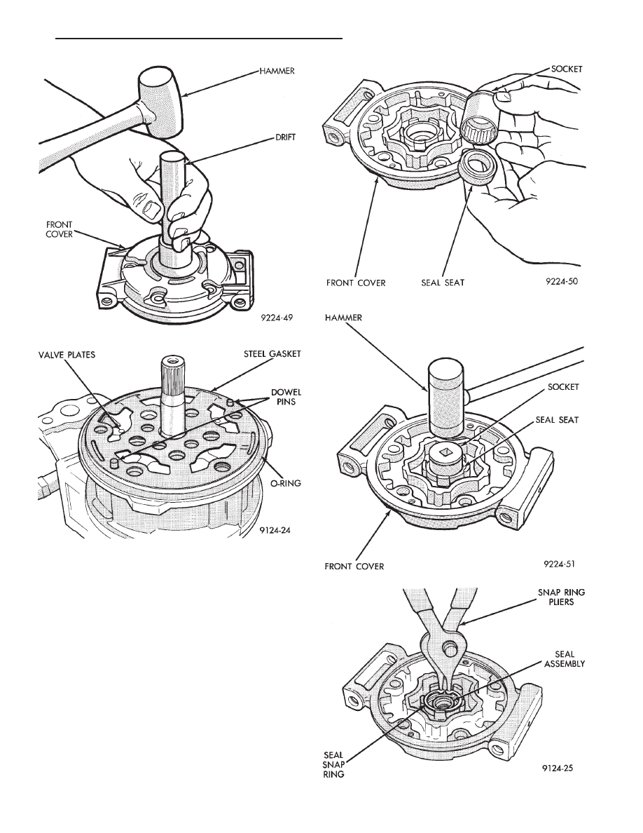
(5) Lubricate crankshaft seal seat cavity of front

housing with refrigeration oil.

(6) Lubricate crankshaft lip seal and seal O-ring

with refrigeration oil. Then install lip seal in front
cover using a socket that contacts the outer diameter
of the lip seal (Figs. 9 and 10).

(7) Install seal snap ring (Fig. 11).
(8) Lubricate front cover O-ring with refrigeration

oil and carefully place it in seal groove.

(9) Install lip seal protector on shaft (Fig. 12).
(10) Install front cover to front compressor body.
(11) Install compressor through-bolts and finger

tighten only. After bolts have been finger tightened,
torque to 29 N

Im (260 in. lbs.).

(12) Install felt shaft seal and retainer (Fig. 13)

into front housing.

Fig. 9 Match Socket to Outer Seal Diameter

Fig. 10 Installing Seal

Fig. 11 Seal Snap Ring

Fig. 7 Removing Seal

Fig. 8 Disassembling Compressor Front End

Ä

HEATING AND AIR CONDITIONING

24 - 29

CAUTION: Refer to Oil Level in the Refrigerant Ser-
vice Procedures section for further details.

(13) Install refrigeration oil (500 SUS) into the

compressor through the suction port.

(14) Check compressor operation for smoothness by

rotating crankshaft at least five full revolutions.

(15) Check front housing clutch coil alignment pin

for proper installation.

(16) Install clutch assembly.
(17) Install compressor.
(18) Evacuate and charge refrigerant system.

COMPRESSOR HIGH-PRESSURE RELIEF VALVE

The high pressure relief valve vents only a small

amount of refrigerant necessary to reduce system
pressure and then reseats itself. The majority of the
refrigerant is conserved in the system. The valve is
calibrated to vent at a pressure of 3100 to 4140 Kpa
(450 to 600 psi). If a valve has vented a small

amount of refrigerant, it does not necessarily mean
the valve is defective.

(HPR) VALVE LOCATION

The HPR Valve is located on the discharge line at

the A/C compressor (Fig. 14).

REMOVAL AND INSTALLATION

(1) Using a refrigerant recovery machine, remove

the refrigerant from the A/C system.

(2) Rotate the high pressure relief valve counterclock-

wise and separate relief valve from the vehicle (Fig. 15).

To install, Reverse the preceding operation using a

new O-ring seal. Evacuate and charge the refrigerant
system.

REFRIGERANT SYSTEM DIAGNOSIS

Refer to the Refrigerant System Diagnosis chart in

this section.

Fig. 13 Felt Retainer and Felt

Fig. 14 High Pressure Relief Valve— Typical

Fig. 15 High Pressure Relief Valve—Typical

Fig. 12 Installing Lip Seal Protector

24 - 30

HEATING AND AIR CONDITIONING

Ä

REFRIGERANT SYSTEM DIAGNOSIS

Ä

HEATING AND AIR CONDITIONING

24 - 31

FIXED DISPLACEMENT COMPRESSOR—MODEL TR105

INDEX

page

page

Compressor

. . . . . . . . . . . . . . . . . . . . . . . . . . . . . 32

Compressor Clutch/Coil Assembly

. . . . . . . . . . . . 32

Compressor Shaft Bearing/Seal

. . . . . . . . . . . . . . 35

Refrigerant System Diagnosis

. . . . . . . . . . . . . . . 36

Thermal Limiter Switch

. . . . . . . . . . . . . . . . . . . . 34

COMPRESSOR

Cleanliness is extremely important when disassem-

bly of the compressor is necessary. The surfaces
around the suction and discharge ports of the com-
pressor should be cleaned thoroughly before opening
the system at these points. If compressor is removed
from vehicle, apply tape to the opened ports to pre-
vent any contamination.

REMOVAL

(1) Disconnect battery negative cable.
(2) Loosen and remove drive belts (refer to Group

7, Cooling System).

(3) Disconnect compressor clutch wire lead.
(4) Using a refrigerant recovery machine, remove

refrigerant from the A/C system.

(5) Remove refrigerant lines from compressor.
(6) Remove compressor attaching bolts.
(7) Remove compressor.

INSTALLATION

(1) Position the compressor on the mount and fit

drive belt.

(2) Tighten the compressor attaching bolts to 41

N

Im (30 ft. lbs.) torque.

(3) Adjust drive belt (see Group 7, Cooling Sys-

tem).

(4) Install refrigerant hoses.
(5) Connect the clutch wire.
(6) Evacuate and charge the system.
(7) Connect the battery negative cable.

COMPRESSOR CLUTCH/COIL ASSEMBLY

CLUTCH INOPERATIVE

The air conditioning compressor clutch electrical

circuit is controlled by the engine controller. The
controller is located in the engine compartment out-
board of the battery.

If the compressor clutch does not engage:
Verify refrigerant charge.
If the compressor clutch still does not engage check

for battery voltage at the low pressure or differential
pressure cut-off switch located on the expansion
valve. If voltage is not detected, refer to:
• Group 8W, Wiring Diagrams.

• The appropriate Powertrain Diagnostic Procedures
Manual for diagnostic information.

If voltage is detected at the cut-off switch, recon-

nect switch. Then check for battery voltage between
the compressor clutch connector terminals.

If voltage is detected, perform A/C Clutch Coil

Tests.

CLUTCH COIL TESTS

(1) Verify battery state of charge. (Test indicator

in battery should be green).

(2) Connect an ammeter (0-10 ampere scale) in se-

ries with the clutch coil terminal. Use a volt meter
(0-20 volt scale) with clip leads measuring voltage
across the battery and A/C clutch.

(3) With A/C control in A/C mode and blower at

low speed, start the engine and run at normal idle.

(4) The A/C clutch should engage immediately and

the clutch voltage should be within two volts of the
battery voltage. If the A/C clutch does not engage,
test the fusible link.

(5) The A/C clutch coil is acceptable if the current

draw is 2.0 to 3.7 amperes at 11.5-12.5 volts at clutch
coil. This is with the work area temperature at 21°C
(70°F). If voltage is more than 12.5 volts, add electri-
cal loads by turning on electrical accessories until
voltage reads below 12.5 volts.

If coil current reads zero, the coil is open and

should be replaced. If the ammeter reading is 4 am-
peres or more, the coil is shorted and should be re-
placed. If the coil voltage is not within two volts of
the battery voltage, test clutch coil feed circuit for
excessive voltage drop.

REMOVAL

(1) Remove the compressor from the mount.
(2) To prevent compressor shaft rotation, install 2

(6 mm) bolts, along with 2 wrenches, to the threaded
holes in the armature plate (Fig. 1). Remove com-
pressor shaft nut.

(3) Tap the armature plate with a plastic and re-

move plate and shim(s).

CAUTION: Do not use screwdrivers between the ar-
mature plate assembly and rotor-pulley to remove
the armature plate. This may damage the armature
plate assembly.

24 - 32

HEATING AND AIR CONDITIONING

Ä


Content   ..  190  191  192  193   ..