Chrysler Le Baron, Dodge Dynasty, Plymouth Acclaim. Manual - part 201


  Index      Chrysler     Chrysler Le Baron, Dodge Dynasty, Plymouth Acclaim - service repair manual 1993 year


Search            


Content   ..  199  200  201  202   ..


Chrysler Le Baron, Dodge Dynasty, Plymouth Acclaim. Manual - part 201


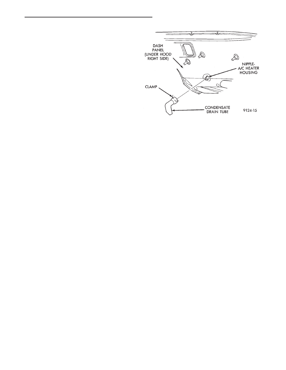
the passenger compartment. It is normal to see con-
densate drainage below the vehicle. If the tube is
damaged, it should be replaced.

REMOVAL AND INSTALLATION

(1) Raise vehicle.
(2) Locate rubber Drain Tube on right side of dash

panel (Fig. 5).

(3) Squeeze clamp and remove drain tube.
To install, reverse the preceding operation. Check

the drain tube nipple on the heater-A/C housing for
any obstructions.

Fig. 5 Condensate Water Drain Tube—Typical

Ä

HEATING AND AIR CONDITIONING

24 - 65

AUTOMATIC TEMPERATURE CONTROL (ATC)

INDEX

page

page

Ambient Temperature Sensor

. . . . . . . . . . . . . . . 67

ATC Computer/Control Panel

. . . . . . . . . . . . . . . . 66

Blend-Air Door Actuator

. . . . . . . . . . . . . . . . . . . . 69

Computer Aided Diagnostic Tests

. . . . . . . . . . . . 72

Diagnostic Trouble Code Definitions

. . . . . . . . . . 73

Diagnostic Trouble Code Service Procedures

. . . 74

Erasing Diagnostic Trouble Codes

. . . . . . . . . . . . 83

Fresh/Recirc Door Actuator

. . . . . . . . . . . . . . . . . 68

General Information—Component Operation

. . . . 66

In-Car Temperature Sensor/Aspirator Assembly

. . 70

Manual A/C Mode

. . . . . . . . . . . . . . . . . . . . . . . . 66

Mode Door Actuator

. . . . . . . . . . . . . . . . . . . . . . 69

Non—Computer Aided Diagnostic Tests

. . . . . . . 72

Power Module

. . . . . . . . . . . . . . . . . . . . . . . . . . . 67

Sun Sensor

. . . . . . . . . . . . . . . . . . . . . . . . . . . . . 71

Water Temperature Sensor

. . . . . . . . . . . . . . . . . 71

GENERAL INFORMATION—COMPONENT
OPERATION

The Automatic Temperature Control (ATC) system

lets the operator change the passenger compartment
environment. A computer, built into the control
panel (Fig. 1), regulates the desired temperature, air
flow direction and blower speed. The operator may
select an AUTO or MANUAL by using the mode but-
ton. Refer to the Owner’s Manual for proper opera-
tion.

The system goes into a maximum cool recirculated

air lock-in mode:
• After selecting a comfort temperature setting of
18°C or 65°F.
• With the A/C compressor turned ‘‘ON’’. The snow-
flake will only illuminate when the system is in the
manual mode.
• With the system not in the defrost mode.

• When the temperature button is held in for ten
seconds.

This will not regulate the temperature until the

system is turned off or the comfort setting is raised
(Fig. 2).

Vacuum is not used to control any of the ATC sys-

tem or components. It is a totally electronic unit.

The A/C compressor can not be turned off in the

AUTO mode.

MANUAL A/C MODE

The manual mode can be activated by pressing the

mode button. The compressor can only be turned
OFF when the climate control system is in the man-
ual mode. The snowflake will be illuminated when
the compressor is ON.

The display panel will show LO, 1-10, and HI sym-

bols when in the manual mode.

ATC COMPUTER/CONTROL PANEL

The ATC computer controller (Fig. 3) manages all

of the systems electronic functions. It provides logic
and/or power to operate the power module, blend-air
door actuator, the mode door and fresh/recirc actua-
tors. It remembers the operators control panel se-
lected settings when the vehicle is not running. Then
it measures return inputs from the sun sensor and
various temperature sensors. After measuring all in-
put information, the computer will ground the output
circuits. This provides logic signals for automatic sys-

Fig. 1 Automatic Temperature Control Computer

Panel

Fig. 2 Automatic Temperature Control Panel Display

Symbols

24 - 66

HEATING AND AIR CONDITIONING

Ä

tem control. The computer control panel is not ser-
viceable except for the illumination bulbs.

For bulb replacement, refer to A/C-Heater Control

Lamp Replacement in Group 8E Instrument Panel.

The ATC Computer/Control Panel is located in the

center of the instrument panel above the radio.

REMOVAL AND INSTALLATION

Refer to A/C-Heater control replacement in the

Switch and Panel Component section of Group 8E,
Instrument Panel and Gauges.

POWER MODULE

The power module (PM) (Fig. 4) receives pulse

width modulated logic signals from the computer
control. The PM then supplies varied voltage to the
blower motor ground circuit for different blower
speeds based on the logic signal. The power module
is not serviceable and must be replaced if found to be
defective.

REMOVAL AND INSTALLATION

(1) Disconnect the negative battery cable.
(2) Remove glove box/ash tray assembly. Refer to

Switch and Panel Component Service section of
Group 8E.

(3) Remove the four PM attaching screws (Fig. 5).

(4) Disconnect electrical connector.
(4) Gently extract PM (to prevent damage to A/C

evaporator) from A/C-heater housing and remove
from under instrument panel.

To install, reverse the preceding operation. Perform

systems check.

AMBIENT TEMPERATURE SENSOR

The ambient air temperature sensor is located in

the A/C housing above the glove box. This is also a
thermistor and will pick up on the environmental
ambient temperature. The computer control uses the
information provided by the ambient sensor to:
• Regulate the low blower speed

• Temperature offsets

• Mode control

The ambient sensor is not serviceable and must be

replaced if found to be defective.

The ambient temperature sensor is plugged into a

two wire receptacle in the A/C-heater housing behind
and above the glove box.

REMOVAL AND INSTALLATION

(1) Remove glove box/ash tray assembly.
(2) Locate and remove two attaching screws on

sensor receptacle (Fig. 6).

(3) Carefully pull receptacle and sensor from hous-

ing.

CAUTION: It is possible for the sensor to hang up
on the edge of the hole in the A/C-heater housing
assembly during removal. This may cause the sen-
sor to disengage from the receptacle and fall into
the housing.

Fig. 3 ATC Computer Controller—Aspirator Air

Intake

Fig. 4 Power Module—Ambient Temperature

Sensor—Fresh/Recirc Door Actuator

Fig. 5 Power Module Removal and Installation

Ä

HEATING AND AIR CONDITIONING

24 - 67

(4) Unplug sensor from receptacle.
To install, reverse the preceding operation and

retest system.

FRESH/RECIRC DOOR ACTUATOR

The fresh/recirc door actuator is an electric servo

motor. It (with the use of linkage) mechanically po-
sitions the A/C unit door in the open or closed posi-
tion. Actuation of the servo motor will occur when
drive signals are supplied to the actuator from the
computer control. This actuator does not contain a
feedback strip therefore can not communicate the
fresh/recirc door position back to the computer con-
trol. The fresh/recirc door actuator is not serviceable
and must be replaced if found to be defective.

The Fresh/Recirc Door Actuator is located on the

passenger side of the A/C-heater case.

CAUTION: Do not remove any of the motor actua-
tors from the heater-A/C unit assembly with any
electrical power applied. Removal should only be
done with the Ignition OFF. The actuators have no
mechanical stops to limit their travel. If the actuator
rotates and is not connected to the unit assembly,
it will become un-calibrated.

REMOVAL AND INSTALLATION

(1) Remove the glove box/ash tray assembly. Refer

to the Switch and Panel Component Service section
of Group 8E.

(2) Remove under panel silencer pad.
(3) Remove the carpeted cover over the air bag

module.

(4) Remove the right front kick panel.
(5) Remove metal instrument panel brace (Fig. 7).
(6) Remove two screws mounting the actuator

mounting bracket to the A/C-heater case (Fig. 8).

(7) Remove three screws holding the actuator to

the mounting bracket (Fig. 9).

CAUTION: Do not allow screw A (Fig. 8) to drop into
A/C-heater housing assembly.

(8) Tilt actuator to release from actuator link. Re-

move actuator from vehicle.

Fig. 9 Actuator Removal and Installation

Fig. 6 Ambient Sensor Removal and Installation

Fig. 7 Brace Removal and Installation

Fig. 8 Actuator Mounting Bracket Removal and

Installation

24 - 68

HEATING AND AIR CONDITIONING

Ä


Content   ..  199  200  201  202   ..