Chrysler Le Baron, Dodge Dynasty, Plymouth Acclaim. Manual - part 177


  Index      Chrysler     Chrysler Le Baron, Dodge Dynasty, Plymouth Acclaim - service repair manual 1993 year


Search            


Content   ..  175  176  177  178   ..


Chrysler Le Baron, Dodge Dynasty, Plymouth Acclaim. Manual - part 177


AP/27-VEHICLE CONVERTIBLE BODY COMPONENT SERVICE

INDEX

page

page

A-Pillar and Windshield Header Weatherstrip

. . . 117

Convertible Top Adjustments

. . . . . . . . . . . . . . . 131

Convertible Top Header

. . . . . . . . . . . . . . . . . . . 118

Convertible Top Latch Hooks

. . . . . . . . . . . . . . . 131

Door Glass Alignment

. . . . . . . . . . . . . . . . . . . . 131

Door Glass Rear Channel

. . . . . . . . . . . . . . . . . 127

Door Striker Guide

. . . . . . . . . . . . . . . . . . . . . . 128

Forward Roof Rail

. . . . . . . . . . . . . . . . . . . . . . . 121

Fourth Roof Bow and Slat

. . . . . . . . . . . . . . . . . 120

Fourth Roof Bow Slat

. . . . . . . . . . . . . . . . . . . . 132

Front Door Belt Moulding and Weatherstrip

. . . . 127

Front Door Glass

. . . . . . . . . . . . . . . . . . . . . . . . 125

Front Door Stationary Glass and Division

Channel

. . . . . . . . . . . . . . . . . . . . . . . . . . . . . 126

Front Door Stationary Glass Channel

Weatherstrip

. . . . . . . . . . . . . . . . . . . . . . . . . . 126

Front Door Striker Guide Socket

. . . . . . . . . . . . 127

Front Seat Belt Retractor

. . . . . . . . . . . . . . . . . . 128

General Information

. . . . . . . . . . . . . . . . . . . . . . 117

Quarter Glass and Roller Bracket

. . . . . . . . . . . 132

Quarter Panel Belt Moulding

. . . . . . . . . . . . . . . 129

Quarter Trim Panel

. . . . . . . . . . . . . . . . . . . . . . 128

Rear Roof Rail

. . . . . . . . . . . . . . . . . . . . . . . . . 121

Rear Seat Back

. . . . . . . . . . . . . . . . . . . . . . . . . 128

Rear Seat Belt Retractor

. . . . . . . . . . . . . . . . . . 129

Rear Tensioner Plate

. . . . . . . . . . . . . . . . . . . . . 132

Rear Window

. . . . . . . . . . . . . . . . . . . . . . . . . . 122

Roof Linkage

. . . . . . . . . . . . . . . . . . . . . . . . . . . 121

Roof Rail Weatherstrip

. . . . . . . . . . . . . . . . . . . 118

Roof Rail Weatherstrip Retainer

. . . . . . . . . . . . . 131

Second Roof Bow and Linkage

. . . . . . . . . . . . . 119

Sling-Well

. . . . . . . . . . . . . . . . . . . . . . . . . . . . . 124

Stationary Quarter Glass and Weatherstrip

. . . . 121

Third Roof Bow

. . . . . . . . . . . . . . . . . . . . . . . . . 120

Top Cover

. . . . . . . . . . . . . . . . . . . . . . . . . . . . . 124

Top Frame

. . . . . . . . . . . . . . . . . . . . . . . . . . . . 125

Top Header Trim Cover

. . . . . . . . . . . . . . . . . . . 118

Top Latch

. . . . . . . . . . . . . . . . . . . . . . . . . . . . . 118

Top Lift Assist Cylinder

. . . . . . . . . . . . . . . . . . . 122

Top Stack Down-Stop

. . . . . . . . . . . . . . . . . . . . 132

Top Stack Up-Stop

. . . . . . . . . . . . . . . . . . . . . . 132

Trunk Hinge Lid

. . . . . . . . . . . . . . . . . . . . . . . . 130

Trunk Lid

. . . . . . . . . . . . . . . . . . . . . . . . . . . . . . 130

Trunk Lid Applique

. . . . . . . . . . . . . . . . . . . . . . 130

Trunk Lid Lining

. . . . . . . . . . . . . . . . . . . . . . . . 129

Trunk Opening Weatherstrip

. . . . . . . . . . . . . . . 130

Windshield Header Lining

. . . . . . . . . . . . . . . . . 117

Windshield Header Moulding

. . . . . . . . . . . . . . . 117

GENERAL INFORMATION

This section will cover components that are unique

to the AP-vehicle convertible. All components that
are common to the AP-vehicle two door hardtop are
covered in the AP-Vehicle Body Components section.

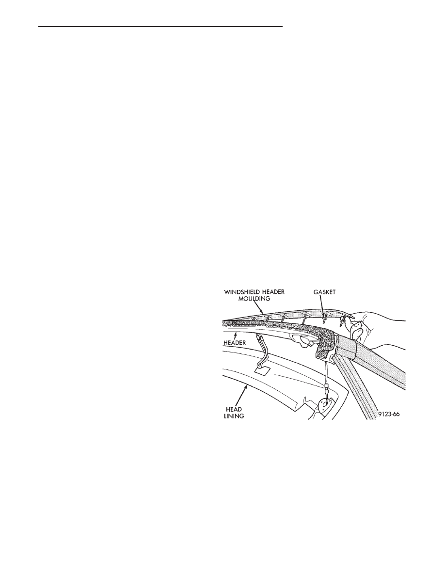
WINDSHIELD HEADER MOULDING

REMOVAL (FIG. 1)

(1) Remove windshield header lining.
(2) Remove nuts holding moulding to windshield

header.

(3) Separate windshield header moulding from ve-

hicle.

INSTALLATION

Apply sealing putty around mounting studs on

back of moulding and reverse the removal operation.

WINDSHIELD HEADER LINING

REMOVAL (FIG. 1)

(1) Remove sun visors and inner sun visor hanger

clips.

(2) Remove upper A-pillar trim covers.
(3) Remove dome lamp.
(4) Separate header lining from vehicle.

INSTALLATION

Reverse the preceding operation.

A-PILLAR AND WINDSHIELD HEADER
WEATHERSTRIP

REMOVAL (FIG. 2)

(1) Remove upper and lower A-pillar trim covers.
(2) Remove header lining and moulding.
(3) Pull A-pillar door opening weatherstrip from

pinch flange.

(4) Pull drip rail weatherstrip from drip rail next

to windshield.

Fig. 1 Windshield Header Moulding

Ä

AP/27 CONVERTIBLE

23 - 117

(5) Pull windshield header weatherstrip from re-

taining channel and separate weatherstrip from vehi-
cle.

INSTALLATION

(1) Apply a bead of Mopar, Glass Adhesive and

Sealer to back of windshield header weatherstrip.

(2) Apply a strip of double sided adhesive tape to

windshield header rearward of the header moulding
stud holes.

(3) Reverse the removal operation.

ROOF RAIL WEATHERSTRIP

REMOVAL (FIG. 3)

(1) Remove screw holding front of roof rail weath-

erstrip to convertible top header.

(2) Pull weatherstrip from retaining channel above

door opening.

INSTALLATION

Reverse the preceding operation.

TOP HEADER TRIM COVER

REMOVAL (FIG. 4)

(1) Lower top.
(2) Remove screws holding header trim to top

header.

CAUTION: The screws on the rearward edge have
caps over the pointed ends to protect top operator
from injury.

(3) Separate trim from header.

INSTALLATION

Reverse the preceding operation.

TOP LATCH

REMOVAL (FIG. 5)

(1) Lower top.
(2) Remove E-ring and clevis pin and separate

latch hook from top header.

(3) Remove latch pivot bolts and separate latch

from top header.

INSTALLATION

Reverse the preceding operation.

CONVERTIBLE TOP HEADER

REMOVAL

(1) Lower convertible top and remove top header

trim cover.

(2) Remove screws holding forward top cover re-

taining strip to top header and separate strip from
top.

(3) Using a heat gun to soften the adhesive, sepa-

rate the top cover from the top header (Fig. 6).

(4) Peel top cover back over forward edge of header

to gain access to stay pad and retention cable attach-
ment.

Fig. 2 A-pillar and Windshield Header Weatherstrip

Fig. 3 Roof Rail Weatherstrip

Fig. 4 Top Header Trim

23 - 118

AP/27 CONVERTIBLE

Ä

(5) Raise convertible top, do not latch top to wind-

shield header.

(6) Remove pop-rivets holding stay pads and reten-

tion cables to top header.

(7) Lower convertible top.
(8) Remove E-clips and clevis pins holding second

bow pivot link to top header (Fig. 7).

(9) Remove bolts holding roof rail pivot bracket to

top header (Fig. 7).

(10) Separate top header from convertible top

frame.

If top header replacement is required, transfer

latching components to replacement header.

INSTALLATION

(1) Place replacement top header in position in

front of roof rail ends on top of cover material.

(2) Install bolts to hold top header to roof rail pivot

brackets.

(3) Install clevis pins and E-clips holding top

header to second bow pivot link.

(4) Raise convertible top. Do not latch.
(5) Rivet retention cables to top header.

CAUTION: Do not stretch top material, top latching
effort increases if top cover or stay pads are to
tight.

(6) Rivet forward ends of stay pads to top header.

A foam tape over rivet heads.

(7) Apply contact adhesive to forward rolled flange

of top header and inside forward two inches of top
cover material. Allow adhesive to cure until slight
tackiness is evident.

(8) Pull top cover material forward until wrinkles

are gone.

(9) Press adhesive coated surfaces together over

front edge of top header.

(10) Verify opening and closing effort of the con-

vertible top and latches.

(11) Verify that wrinkles in top cover, with head-

ers latched, are minimal. Slight wrinkles in top cover
will decrease when top is heated by the sun or arti-
ficial heat source. If necessary, adjust top latch
hooks.

(12) Lower convertible top.
(13) Place retaining strip at front edge of top

header over edge turned material. Using a scratch
awl, align screws holes in retaining strip to holes in
top header.

(14) Install screws to hold retaining strip to top

header.

(15) Install top header trim panel.

SECOND ROOF BOW AND LINKAGE

REMOVAL

(1) Lower convertible top.
(2) Remove E-clip and clevis pin holding second

roof bow pivot link to top header (Fig. 8).

(3) Remove screws holding second roof bow actuat-

ing link to pivot link (Fig. 8).

(4) Remove screws holding second roof bow to top

cover listing retainer (Fig. 9).

Fig. 5 Top Latch

Fig. 6 Stay Pads and Retention Cables

Fig. 7 Pivot Link and Roof Rail Pivot Bracket.

Ä

AP/27 CONVERTIBLE

23 - 119

(5) Remove staples holding stay pads to second roof

bow.

(6) Separate second roof bow from top frame.

INSTALLATION

(1) Position second roof bow on convertible top.
(2) Staple stay pads to second roof bow tack strip

in same locations as the original assembly.

(3) Install screws to hold top cover listing retainer

to second roof bow.

(3) Install screws, washers and spacers to hold roof

bow actuating link to pivot link.

(4) Install clevis pins and E-clips to hold second

roof bow pivot link to top header.

(5) Verify convertible top operation.

THIRD ROOF BOW

REMOVAL

(1) Disengage top header latches.
(2) Lower convertible top halfway down.
(3) Remove bolts holding third roof bow to rear

roof rails.

(4) Separate third roof bow from rear roof rails.

(5) Rotate third roof bow to gain access to staples

holding stay pads to tack strip.

(6) Remove staples holding stay pads to third roof

bow.

(7) Remove screws holding top cover listing re-

tainer to third roof bow (Fig. 10).

(8) Separate third roof bow from top frame.

INSTALLATION

(1) Position third roof bow on convertible top.
(2) Staple stay pads to third roof bow tack strip in

same locations as the original assembly.

(3) Install screws to hold top cover listing retainer

to third roof bow.

(3) Install bolts to hold third roof bow rear roof

rails.

(4) Align third roof bow to be centered over the

rear roof rails.

(5) Verify convertible top operation.

FOURTH ROOF BOW AND SLAT

The fourth roof bow and slat is adjustable to de-

crease wrinkles in the convertible top cover sail
panel and rear window areas.

REMOVAL (FIG. 11)

(1) Lower rear window glass. position glass flat on

the bottom of the sling well.

(2) Lower convertible top halfway down.
(3) Remove pivot bolts and bushings holding fourth

roof bow slat to rear roof rail (Fig. 12).

(4) Remove tension spring from between rear roof

rail and fourth roof bow slat (Fig. 13).

(5) Remove shoulder bolts holding fourth roof bow

to slat.

(6) Separate bow from slats (Fig. 12).
(7) Allow roof bow to drop downward.
(8) Tip bow toward interior of vehicle and away

from top cover.

(9) Lower convertible top enough to allow to loosen

around fourth roof bow.

Fig. 8 Second Roof Bow

Fig. 9 Second Roof Bow Retainer

Fig. 10 Third Roof Bow Retainer

23 - 120

AP/27 CONVERTIBLE

Ä


Content   ..  175  176  177  178   ..