Chrysler Le Baron, Dodge Dynasty, Plymouth Acclaim. Manual - part 176


  Index      Chrysler     Chrysler Le Baron, Dodge Dynasty, Plymouth Acclaim - service repair manual 1993 year


Search            


Content   ..  174  175  176  177   ..


Chrysler Le Baron, Dodge Dynasty, Plymouth Acclaim. Manual - part 176


REAR SEAT BACK INSTALLATION

Reverse the preceding operation.

SEAT BACK BOLSTER CUSHION REMOVAL
(FIG. 37)

(1) Remove rear seat cushion and back as neces-

sary.

(2) Remove bolts holding outboard seat back bol-

ster to quarter panel.

(3) Lift bolster upward to disengage hook retainer

on back of bolster and separate from vehicle.

SEAT BACK BOLSTER CUSHION
INSTALLATION

Reverse the preceding operation

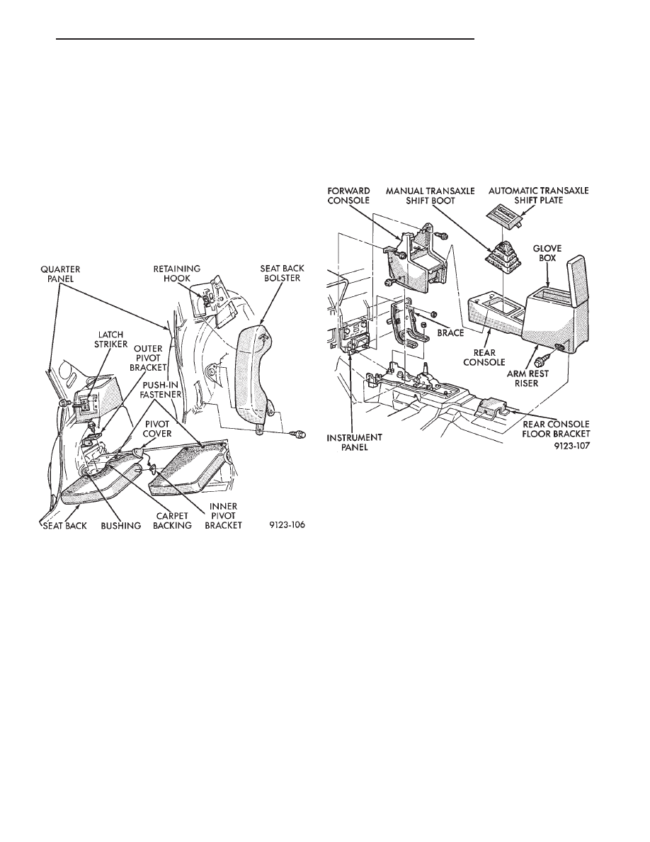
FRONT CENTER CONSOLE

REMOVAL (FIG. 38)

(1) Position front seats full forward.
(2) Remove gear selector knob and PRNDL on ve-

hicles with automatic transaxle. Remove illumina-
tion lamp socket and position socket out of the way.

(3) Lift gear shift boot adapter from console and

push adapter through opening in console on vehicles
with manual transaxle.

(4) Remove bolts holding arm rest riser to floor

bracket.

(5) Separate rear console from floor and remove

from vehicle.

(6) Position front seats full rearward.
(7) Remove radio bezel from instrument panel. Re-

fer to Group 8E, Instrument Panel. Remove screws
holding console to instrument panel.

(8) Remove screws holding forward console to

lower instrument panel rail.

(9) Remove screws holding forward console to for-

ward brace.

(10) Separate forward console from vehicle.

INSTALLATION

Reverse the preceding operation. Verify PRNDL

adjustment before returning vehicle to use.

FLOOR CARPET

REMOVAL (FIG. 39)

(1) Remove cowl trim panels and scuff plates.
(2) Remove front seats and inboard seat belts.
(3) Remove center arm rest and front console.
(4) Remove outboard seat belt lower attaching

bolts.

(5) Remove rear seat cushion.
(6) Pull carpet from under B-pillar trim covers.
(7) Fold carpet and remove through front door

opening.

INSTALLATION

Reverse the preceding operation.

OVERHEAD CONSOLE

REMOVAL (FIG. 40)

(1) Remove screws holding overhead console to re-

inforcement bracket.

(2) Slide overhead console rearward to separate re-

inforcement bracket retainer tab from console.

(3) Lower console from roof and disconnect wire

connectors.

Fig. 37 Rear Seat Back and Bolster

Fig. 38 Front Center Console

Ä

AP-BODY

23 - 113

INSTALLATION

Reverse The preceding operation.

HEAD LINING

REMOVAL (FIG. 41)

(1) Disconnect battery negative cable.
(2) Pull dome lamp downward to disengage from

retaining ring in head lining. Separate lens from
lamp body and remove bulb. Separate bulb holder
from lamp body. Remove attaching screw holding re-
taining ring to roof bow.

(3) Remove screws holding coat hooks to roof above

rear doors.

(4) Remove roof rail and A-pillar mouldings.
(5) Remove screws holding sun visors to roof

header and disconnect wire connector, if equipped.
Remove inboard sun visor hangers.

(6) Remove overhead console, if equipped.
(7) Pull front reading lamp downward to disengage

from retaining ring in head lining and disconnect
wire connector. Remove screws holding retaining
ring to roof header.

(8) Remove pinch welt holding headlining to sun

roof opening, if equipped.

(9) Remove inside rear view mirror from wind-

shield bracket if necessary.

(10) Disengage hook and loop fasteners holding

head lining to roof above rear window and slide head
lining forward about 25 mm (1 in.).

(11) Shift the front of head lining to one side to

pull head lining from behind B-pillar trim. Pull head
lining from behind other B-pillar trim.

(12) Allow front of head lining to drop downward.

Slide head lining forward from behind quarter panel
trim.

(13) Remove head lining from vehicle.

INSTALLATION

Reverse the preceding operation.

SUN ROOF WEATHERSTRIP

REMOVAL (FIG. 42)

(1) Remove sun roof sunshade and glass. Refer to

Owner’s Manual for instructions.

(2) Pull weatherstrip from pinch flange around sun

roof opening.

INSTALLATION

Reverse the preceding operation.

SUN ROOF AIR DEFLECTOR

REMOVAL (FIG. 42)

(1) Remove sun roof sunshade and glass. Refer to

Owner’s Manual for instructions.

Fig. 39 Floor Carpet and Silencers—Typical

Fig. 40 Overhead Console—Typical

Fig. 41 Head Lining—Typical

23 - 114

AP-BODY

Ä

(2) Disengage snap-on linkage at rear of air deflec-

tor in sun roof opening.

(3) Remove screws holding air deflector to front of

sun roof opening.

INSTALLATION

Reverse the preceding operation.

SUN ROOF DRAIN TUBES

REMOVAL (FIG. 42)

(1) Remove head lining as necessary.
(2) Remove A-pillar or B-pillar trim covers as nec-

essary.

(3) Remove cowl panel and sill plate trim as neces-

sary.

(4) Disconnect effected drain tube from nipple at

sun roof opening.

(5) Pull drain tube upward to remove from pillar

involved.

INSTALLATION

Reverse the preceding operation. Route the tube to

avoid kinks or puncture from sharp edges.

LIFT GATE REMOTE RELEASE CABLE

REMOVAL

(1) Remove interior trim as necessary to gain ac-

cess to release cables.

(2) Remove left front door scuff plate.
(3) Remove screw holding trim cover to release ca-

ble handle and separate cover from handle.

(4) Remove screw holding release handle to door

sill.

(5) Pry open retainer tab holding cable core end in

handle pivot. Pry cable case end from handle.

(6) Remove trunk lining as necessary to gain ac-

cess to the release cable.

(7) Disconnect cable end from latch.
(8) Separate cable from vehicle.

INSTALLATION

Reverse the preceding operation.

REAR WINDOW GLASS

REMOVAL (FIG. 43)

(1) Raise lift gate to up position.
(2) Remove screws holding outward edges to rear

window moulding to lift gate frame.

(3) Position protective card board covers along the

top of the quarter panels to protect painted surfaces.

Fig. 42 Sun Roof

Ä

AP-BODY

23 - 115

(4) Support lift gate in the up position and remove

bolts holding lift gate hinge closed. Lower lift gate to
opening weatherstrip.

(5) Remove screws holding top of rear window

moulding to lift gate frame. Separate moulding from
lift gate.

(6) Pull lower rear window moulding from under

glass.

(7) Cut urethane bonding from around rear win-

dow. Refer to Windshield section of this group.

INSTALLATION

Prepare the lift gate fence and rear window as de-

scribed in the Windshield Installation section of this
group. Reverse the removal operation.

LIFT GATE LUGGAGE RACK

REMOVAL (FIG. 44)

(1) Remove screws holding cross bar to outboard

skid strips.

(2) Pry rubber inserts from skid strips.
(3) Remove screws holding skid strips to lift gate.

INSTALLATION

Reverse the preceding operation

Fig. 43 Rear Window Glass

Fig. 44 Lift Gate Luggage Rack

23 - 116

AP-BODY

Ä


Content   ..  174  175  176  177   ..