Chrysler Le Baron, Dodge Dynasty, Plymouth Acclaim. Manual - part 174
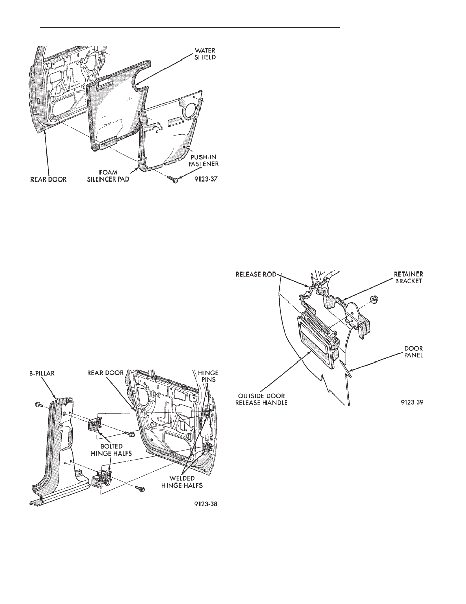
REAR DOOR REMOVAL (FIG. 21)
(1) Remove B-pillar trim panel and disconnect all
wire connectors leading to door. Push wire harness
through access hole in B-pillar into hinge opening.
(2) Support door on a suitable lifting device.
(3) Drive bottom hinge pin upward and remove pin
from hinge.
(4) Drive top hinge pin downward and remove pin
from hinge.
(5) Separate door from vehicle.
REAR DOOR INSTALLATION
Reverse the preceding operation. The door should
not require re-alignment. If door does need align-
ment, refer to Rear Door Hinge Installation para-
graph in this section.
REAR DOOR HINGE REMOVAL (FIG. 21)
(1) To remove upper hinge bolted half, remove
B-pillar trim panel. To remove lower hinge bolted
half it is not necessary to remove B-pillar trim.
(2) Support rear door on a suitable lifting device.
(3) Drive out hinge pin on the effected hinge.
(4) Remove bolts holding hinge to B-pillar and sep-
arate hinge form vehicle.
REAR DOOR HINGE INSTALLATION
Reverse the preceding operation. Align door to
achieve 6 mm (0.240 in.) gap to all surrounding pan-
els and flush across gaps.
OUTSIDE REAR DOOR LATCH RELEASE HANDLE
REMOVAL (FIG. 22)
(1) Remove door trim panel, silencer pad, and wa-
ter shield.
(2) Raise door glass to full up position.
(3) Remove rear door speaker, if equipped.
(4) Disconnect latch release rod from door latch as-
sembly.
(5) Remove nuts holding outside door latch handle
to retainer bracket and separate bracket from door.
(6) Separate latch handle from door panel.
INSTALLATION
Reverse the preceding operation.
REAR DOOR LATCH
REMOVAL (FIG. 23)
(1) Remove door trim panel, silencer pad and wa-
ter shield.
(2) Raise door glass to full up position.
(3) Remove door speaker, if equipped.
(4) Disconnect all actuator rods from door latch as-
sembly.
(5) Remove screws holding door latch assembly to
inner door rear panel and separate from door.
INSTALLATION
Reverse the preceding operation.
Fig. 20 Rear Door Silencer and Water
Shield—Typical
Fig. 21 Rear Door Hinges—Typical
Fig. 22 Outside Rear Door Latch Release
Handle—Typical
Ä
AP-BODY
23 - 105