Chrysler Le Baron, Dodge Dynasty, Plymouth Acclaim. Manual - part 173


  Index      Chrysler     Chrysler Le Baron, Dodge Dynasty, Plymouth Acclaim - service repair manual 1993 year


Search            


Content   ..  171  172  173  174   ..


Chrysler Le Baron, Dodge Dynasty, Plymouth Acclaim. Manual - part 173


FRONT DOOR HINGE INSTALLATION

Reverse the preceding operation. Align door to

achieve 6 mm (0.240 in.) gap to all surrounding pan-
els and flush across gaps.

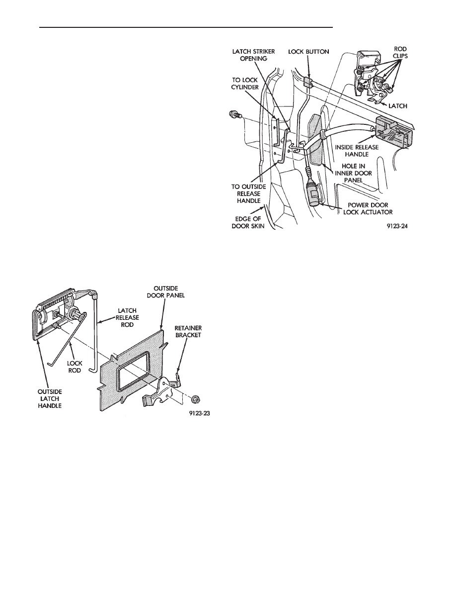
OUTSIDE FRONT DOOR LATCH RELEASE HANDLE

REMOVAL (FIG. 10)

(1) Remove front door trim panel, silencer pad, and

water shield.

(2) Raise door glass to full up position.
(3) Disconnect security alarm switch and illumi-

nated entry switch from back of outside front door
latch release handle, if equipped. For additional in-
formation refer to Group 8Q, Vehicle Theft Security
System

(4) Disconnect lock rod and latch release rod from

door latch assembly.

(5) Remove nuts holding outside door latch handle

to retainer bracket and separate bracket from door.

(6) Swing lock rod upward, parallel to back of

latch handle, and separate latch handle from door
panel.

INSTALLATION

Reverse the preceding operation.

FRONT DOOR LATCH

REMOVAL (FIG. 11)

(1) Remove front door trim panel, silencer pad and

water shield.

(2) Raise door glass to full up position.
(3) Disconnect all actuator rods from door latch as-

sembly.

(4) Remove screws holding door latch assembly to

inner door rear panel and separate latch from door.

INSTALLATION

Reverse the preceding operation.

FRONT DOOR SIDE VIEW MIRROR

REMOVAL (FIG. 12)

(1) Remove front door trim panel.
(2) Remove side view mirror remote adjusting

knob cover, if equipped.

(3) Remove screws holding mirror bezel to door

frame and separate bezel from door. Loosen set-screw
holding bezel to mirror adjuster cable, if equipped.

(4) Remove silencer seal from door frame behind

mirror bezel.

(5) Disconnect power mirror wire connector, if

equipped.

(6) Remove access hole cover.
(7) Remove nuts holding mirror to door frame and

separate mirror from door.

INSTALLATION

Reverse the preceding operation.

FRONT DOOR GLASS

REMOVAL (FIG. 13)

(1) Remove door trim panel, silencer pad, and wa-

ter shield.

(2) Position door glass half way up in door glass

opening.

(3) Insert door glass removal tool C-4867 between

the glass slide and channel retaining lip at approxi-
mately 50 mm (2 in.) down from top rearward corner
of glass. Push handle of tool toward glass to open
channel. Push downward at the front of the glass to
separate the slide from the channel.

(4) Insert door glass removal tool C-4867 between

the glass slide and channel retaining lip at approxi-

Fig. 10 Outside Front Door Latch Release

Handle—Typical

Fig. 11 Front Door Latch—Typical

Ä

AP-BODY

23 - 101

mately 50 mm (2 in.) up from bottom rearward cor-
ner of glass through opening in inner door panel.
Push handle of tool toward glass to open channel.
Pull upward at front of glass to separate the slide
from the channel. Do not allow upper slide to snap
bank into channel.

(5) Rotate front of glass downward and slide glass

forward to separate glass lift channel from regulator
lift arm roller.

(6) Remove door glass through opening at top of

door.

INSTALLATION

(1) Lower door glass into opening at top of door.
(2) Tip rear of glass downward and insert window

regulator lift arm roller into glass lift channel.

(3) Guide door glass into glass run weatherstrip at

front of door.

(4) Push top of glass rearward to snap top slide

into glass run channel.

(5) Push downward at front of glass to snap bottom

slide into glass run channel.

(6) Install water shield, silencer pad and trim

panel.

FRONT POWER DOOR LOCK ACTUATOR

REMOVAL (FIG. 14)

(1) Disconnect battery negative cable.
(2) Remove front door trim panel.
(3) Remove water shield as necessary.
(4) Remove rivets holding lock motor to inner door

panel with a 6 mm (1/4 in.) drill.

(5) Disconnect lock motor linkage rod from door

latch.

(6) Disconnect lock motor wire connector.
(7) Separate lock motor from door.

INSTALLATION

Reverse the preceding operation.

FRONT DOOR BELT MOULDING AND
WEATHERSTRIP

BELT MOULDING AND WEATHERSTRIP
REMOVAL

(1) Remove trim panel, silencer pad, and water

shield as necessary to gain access to belt moulding
attaching screws.

(2) Remove door glass.
(3) Remove screws holding belt moulding and

weatherstrip to outer door panel and separate moul-
ding from door.

BELT MOULDING AND WEATHERSTRIP
INSTALLATION

Reverse the preceding operation.

Fig. 12 Front Door Side View Mirror—Typical

Fig. 13 Front Door Glass

Fig. 14 Front Power Door Lock Actuator—Typical

23 - 102

AP-BODY

Ä

FRONT DOOR GLASS CHANNEL AND RUN
WEATHERSTRIP

GLASS CHANNEL AND RUN WEATHERSTRIP
REMOVAL (FIG. 15)

(1) Remove door belt moulding and weatherstrip

assembly.

(2) Pull door glass run weatherstrip from forward

lower channel and upper door frame back to rear up-
per corner of door frame.

(3) Separate weatherstrip from top of rear door

frame down to first clip. Using a suitable hook tool,
disengage clip barb from door frame channel. Pull
weatherstrip outward to disengage clip. Repeat this
procedure at each clip down the rear channel.

(4) Separate glass channel and run weatherstrip

from door.

GLASS CHANNEL AND RUN WEATHERSTRIP
INSTALLATION

(1) Insert glass run weatherstrip into top of glass

opening upper channel. Align molded corners of
weatherstrip to corners of glass opening.

(2) Push weatherstrip and glass run channel into

upper rear glass opening channel. Seat the top re-
taining clip by placing a fiber trim stick (C-4755)
over the clip attaching rivet inside the glass run
channel and push or tap firmly inward until clip
seats. Verify the alignment of the weatherstrip in
the top rear corner. Repeat this procedure on each
clip going down the run.

(3) Install door belt moulding and weatherstrip as-

sembly.

FRONT DOOR GLASS RUN LOWER CHANNELS

FRONT OR REAR LOWER CHANNEL REMOVAL
(FIG. 16)

(1) Remove door glass channel and run weather-

strip as necessary to gain access to lower channels
and attaching rivets.

(2) Drift punch rivet center expansion pins from

each pop-rivet fastener holding channel to door panel
or mirror support frame.

(3) Drill pop-rivet fasteners out of door panel or

mirror support frame and separate front or rear
channel from door.

FRONT OR REAR LOWER CHANNEL
INSTALLATION

(1) Install lower channel into at design location.
(2) Install pop-rivets using a suitable pop-rivet

gun.

(3) Install Glass channel and run weatherstrip.
(4) Install belt moulding and weatherstrip assem-

bly.

(5) Install door glass.
(6) Install door water shield silencer pad and trim

panel.

FRONT DOOR WINDOW REGULATOR/MANUAL

MANUAL WINDOW REGULATOR REMOVAL
(FIG. 17)

(1) Remove trim panel, silencer pad, and water

shield.

(2) Raise glass to 25 mm (1 in.) from full up posi-

tion. Using suitable tape, secure door glass to upper
window frame.

(3) Remove bolts holding window regulator to in-

ner door panel.

(4) Slide roller from window lift channel. Rotate

regulator

to bring lift arm through access hole first.
(5) Remove regulator assembly from door.

Fig. 15 Front Door Glass Channel and Run

Weatherstrip—Typical

Fig. 16 Front Door Lower Channels—Typical

Ä

AP-BODY

23 - 103

MANUAL WINDOW REGULATOR
INSTALLATION

Reverse the preceding operation.

FRONT DOOR WINDOW REGULATOR/POWER

POWER WINDOW REGULATOR REMOVAL
(FIG. 18)

(1) Remove trim panel and water shield and con-

nect window switch to wire connector.

(2) Raise glass to 25 mm (1 in.) from full up posi-

tion. Using suitable tape, secure door glass to upper
window frame.

(3) Disconnect battery negative cable.
(4) Remove bolts holding window regulator to in-

ner door panel.

(5) Slide roller from window lift channel. Rotate

regulator

to bring lift arm through access hole first.
(6) Remove regulator assembly from door.

POWER WINDOW REGULATOR INSTALLATION

Reverse the preceding operation.

REAR DOOR TRIM PANEL

REMOVAL (FIG. 19)

(1) Move glass to down position.
(2) Disconnect battery negative cable.
(3) Remove inside latch release handle bezel. Pull

outward at forward edge and push bezel rearward.

(4) Remove screw cover from window crane. Re-

move screw holding crank to window regulator, if
equipped.

(5) Remove screw covers from armrest. Remove

screws holding armrest to door.

(6) Disengage frog-leg clips holding trim panel to

door. Separate trim panel from door.

(7) Disconnect courtesy lamp wire connector.

INSTALLATION

Reverse the preceding operation.

REAR DOOR SILENCER AND WATER SHIELD

REMOVAL (FIG. 20)

(1) Remove door trim panel.
(2) Pull water shield from adhesive around perim-

eter of door inner panel.

INSTALLATION

Reverse the preceding operation.

REAR DOOR AND HINGE

The rear door hinge is welded to the door and

bolted to the B-pillar. The door half of the hinge piv-
ots on a removable hinge pin. The hinge pin is
driven in from the bottom on the top hinge and from
the top on the bottom hinge. All adjustments to the
hinge are performed on the hinge pillar half of the
hinge. If the welded half of the hinge must be bent to
align door, consult an authorized body repair facility.

Fig. 17 Front Door Manual Window

Regulator—Typical

Fig. 18 Front Door Power Window

Regulator—Typical

Fig. 19 Rear Door Trim Panel

23 - 104

AP-BODY

Ä


Content   ..  171  172  173  174   ..