Chrysler Le Baron, Dodge Dynasty, Plymouth Acclaim. Manual - part 128


  Index      Chrysler     Chrysler Le Baron, Dodge Dynasty, Plymouth Acclaim - service repair manual 1993 year


Search            


Content   ..  126  127  128  129   ..


Chrysler Le Baron, Dodge Dynasty, Plymouth Acclaim. Manual - part 128


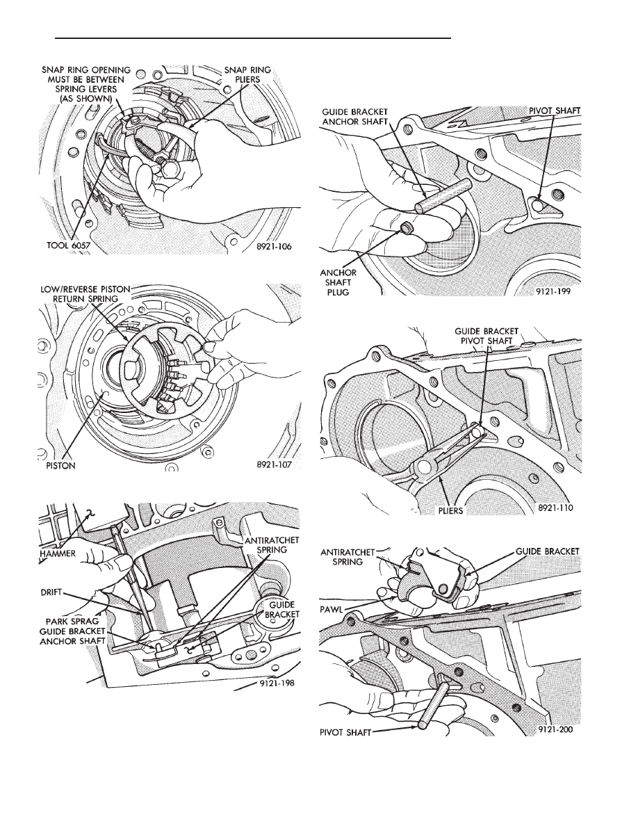
CAUTION: When installing, be sure guide bracket
and split sleeve touch the rear of the transaxle
case.

Fig. 70 Remove or Install Snap Ring

Fig. 71 Low/Reverse Piston Return Spring

Fig. 72 Drive Out Anchor Shaft

Fig. 73 Anchor Shaft and Plug

Fig. 74 Guide Bracket Pivot Shaft

Fig. 75 Pivot Shaft and Guide Bracket

Ä

TRANSAXLE

21 - 117

Fig. 76 Guide Bracket Assembled

Fig. 77 Guide Bracket Disassembled

Fig. 78 Low/Reverse Clutch Piston

Fig. 79 Piston Retainer Attaching Screws

Fig. 80 Piston Retainer

Fig. 81 Piston Retainer Gasket

21 - 118

TRANSAXLE

Ä

CAUTION: Drift bearing cup all the way around.

To assemble, reverse the above procedure. Be sure

to check both grounded clutch clearances. Before in-

stalling the input clutches retainer, follow the instruc-
tions in Determining No. 4 Thrust Plate Thick-
ness
.

Fig. 82 Remove Output Bearing Inner Cup

Fig. 83 Remove Output Bearing Outer Cup

Fig. 84 Install Both Output Bearing Cups

Fig. 85 Checking Output Gear Bearings End Play

Fig. 86 Checking Output Gear Bearings Turning

Torque

Fig. 87 Check Low/Reverse Clutch Clearance

Ä

TRANSAXLE

21 - 119

Press down clutch pack with finger and zero dial

indicator. Low/Reverse clutch pack clearance is
1.04 to 1.65mm (.042 to .065 inch).

Select the proper low/reverse reaction plate to

achieve specifications:

Press down clutch pack with finger and zero dial

indicator. The 2/4 clutch pack clearance is 0.76 to
2.64mm (.030 to .104 inch). 
If not within specifica-
tions, the clutch is not assembled properly. There is
no adjustment for the 2/4 clutch clearance.

DETERMINING NO. 4 THRUST PLATE
THICKNESS—INPUT SHAFT END PLAY

To determine the proper thickness of the No. 4 thrust

plate, select the thinnest No. 4 thrust plate. Using
petrolatum (Fig. 87) to hold thrust plate in position,
install input clutches assembly. Be sure the input
clutches assembly is completely seated (Fig. 88).

CAUTION: If view through input speed sensor hole is
not as shown above, the input clutches assembly is
not seated properly.

By removing the oil pump O-ring, you will be able to

install and remove the oil pump and gasket very easily
to select the proper No. 4 thrust plate.

CAUTION: Be sure to reinstall O-ring on oil pump
after selecting the proper No. 4 thrust plate.

Input shaft end play must be .005 to .025 inch.

LOW/REVERSE REACTION PLATE CHART

Fig. 88 Check 2/4 Clutch Clearance

Fig. 89 Select Thinnest No. 4 Thrust Plate

Fig. 90 View Through Input Speed Sensor Hole

Fig. 91 Remove Oil Pump O-Ring

21 - 120

TRANSAXLE

Ä


Content   ..  126  127  128  129   ..