Chrysler Le Baron, Dodge Dynasty, Plymouth Acclaim. Manual - part 88
mount have been loosened for any reason, or if vehicle
has experienced front structural damage, driveshaft
lengths must be checked and corrected, if required. A
shorter than required driveshaft length can result in ob-
jectionable noise. A longer than required driveshaft
length may result in potential damage.
Use of the following procedure will ensure satisfac-
tory driveshaft engagement under all normal vehicle
operating conditions.
(1) The vehicle must be completely assembled.
Front wheels must be properly aligned and in the
straight ahead position. The vehicle must be in a po-
sition so that the full weight of the body is distrib-
uted to all four tires. A platform hoist, or front end
alignment rack, is recommended.
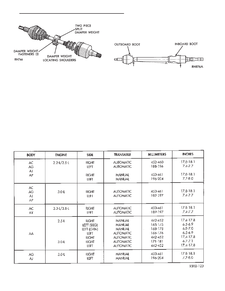
(2) Using a tape measure or other suitable measuring
device. Measure the direct distance from the inner edge
of the outboard boot to the inner edge of the inboard
boot on both driveshafts. This measurement must be
taken at the bottom (six o’clock position) of the drive-
shafts (Fig. 1).
Note that the required dimension varies with car-line,
engine, transaxle, and driveshaft manufacturer (Fig. 2).
(3) If the lengths of both shafts are within the
range specified, no further action is required.
If either left or right driveshaft length is not
within the specified range. Refer to Group 09, Engine
Removal and Installation to properly position engine
according to specified driveshaft lengths.
(4) If proper driveshaft lengths cannot be achieved
within the travel limits available in the slotted engine
mounts. Check for any condition that could effect the
side to side position of the measurement locations (e.g.,
engine support brackets, siderail alignment, etc.).
(5) After ensuring proper driveshaft lengths the
transmission shift linkage must be adjusted to en-
sure proper operation. Refer to Transaxle, Group 21.
Fig. 2 Driveshaft Identification and Dimensions
Fig. 19 Left Driveshaft with Damper Weight
Fig. 1 Driveshaft Positioning
Ä
SUSPENSION AND DRIVESHAFTS
2 - 49