Chrysler Le Baron, Dodge Dynasty, Plymouth Acclaim. Manual - part 86


  Index      Chrysler     Chrysler Le Baron, Dodge Dynasty, Plymouth Acclaim - service repair manual 1993 year


Search            


Content   ..  84  85  86  87   ..


Chrysler Le Baron, Dodge Dynasty, Plymouth Acclaim. Manual - part 86


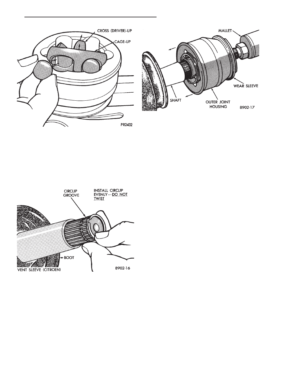
(8) Insert balls into raceway by tilting cage and in-

ner race assembly (Fig. 7).

(9) Fasten boot to shaft. See Boots Install.
(10) On G.K.N. units insert the new circlip, pro-

vided with kit in shaft groove. Do not over expand
or twist 
circlip during assembly (Fig. 8). The S.S.G.
unit has a reusable circlip retainer that is an inte-
gral part of driver assembly.

(11) Position outer joint on splined end with hub

nut on stub shaft. Engage splines, and tap sharply
with mallet (Fig. 9).

(12) Check that circlip is properly seated by at-

tempting to pull joint from the shaft.

(13) Locate large end of boot over joint housing

checking that boot is not twisted.

(14) Fasten boot to housing. See Boots Install.

INTERMEDIATE SHAFT ASSEMBLY RECONDITION

Reconditioning of intermediate shaft assembly (Fig.

1), for Equal Length Drive Shaft System vehicles is
the same for manual and automatic transaxles.

INTERMEDIATE SHAFT ASSEMBLY

REMOVE

(1) Remove right driveshaft. See Driveshaft As-

semblies Remove.

(2) Remove speedometer pinion from the extension

housing (Fig. 2).

(3) Remove the two bolts which mount the bearing

assembly bracket to the engine block (Fig. 1).

(4) Remove assembly from transaxle extension by

pulling outward on the yoke (Fig. 3).

UNIVERSAL JOINT AND ROLLER

Disassemble

(1) Mark relationship of shaft to shaft to ensure

proper alignment at assembly. Apply penetrating oil
to bushings and remove snap rings.

(2) Support yoke in vise and place a socket large

enough to receive bushing on top of yoke. A 1-1/8
inch socket is suitable (Fig. 4).

(3) Striking socket with hammer will cause yoke to

move down and bushing to move up out of yoke into
socket.

(4) After removing one bushing, turn parts in a

vise and remove other bushing in same manner.

Assemble

(1) Hold cross in position between yoke ears with

one hand and start one bushing assembly into yoke
with other hand (Fig. 5).

(2) Continue to hold cross in position, then ham-

mer bushing assembly into yoke and install snap
ring.

(3) Install opposite bushing and snap ring in the

same manner.

Fig. 7 Inserting Balls into Raceway

Fig. 8 Installing New Circlip

Fig. 9 Position Joint onto Shaft Splines

Ä

SUSPENSION AND DRIVESHAFTS

2 - 41

(4) Repeat process for stub shaft yoke after align-

ing marks on yoke and shaft.

BRACKET, BEARING, AND SLINGER
ASSEMBLY

Disassemble

(1) Remove the two screws that hold the bearing

assembly to the support bracket.

(2) Press the intermediate shaft out of the bearing

assembly and outer slinger. Do not dent or damage the
inner slinger. Also avoid damaging the end of the stub
shaft, the rubber seal on the right driveshaft mates
with this surface. Excessive wear to the rubber seal
would result and allow moisture to enter, corroding the
internal splines.

(3) If either slinger is damaged, it should be re-

placed. Carefully press the shaft through the slinger,
discard the slinger.

The bearing assembly is not serviceable and

must be replaced as an assembly.

Assemble

(1) Place new slinger on stub shaft and drive it on until

it bottoms out on the shoulder of the shaft (Fig. 6). A tool
for this purpose can be fabricated from a piece of pipe that
has the dimensions noted in (Fig. 6).

Fig. 1 Intermediate Shaft Assembly

Fig. 2 Remove Speedometer Pinion

Fig. 3 Removing Intermediate Shaft Assembly

2 - 42

SUSPENSION AND DRIVESHAFTS

Ä

CAUTION: Do not dent or bend the slinger during
this installation, since it could prevent the bearing
assembly from seating properly.

(2) Press bearing assembly into position on the

shaft, there should be a minimum of 1 mm (1/32 in.)
clearance between slinger and bearing assembly
when properly installed.

CAUTION: Apply pressure only to the inner race of
the bearing during this procedure. Or damage may
result which could cause premature bearing failure.

(3) Press the outer slinger into place with the

same tool used for bearing installation. The slinger
must bottom out on the shoulder of the shaft.

INTERMEDIATE SHAFT ASSEMBLY

Install

(1) Securely fasten bracket to bearing assembly

and tighten to 28 N

Im (21 ft. lbs.) torque (Fig. 7)

(Also see Fig. 1).

(2) Hold the stub yoke while aligning and guiding

the splined end into the transaxle (Fig. 8).

Fig. 4 Disassemble Universal Joint

Fig. 5 Assemble Universal Joint

Fig. 6 Slinger Installation Intermediate Shaft

Fig. 7 2.5L Turbo III Intermediate Driveshaft Bracket

Ä

SUSPENSION AND DRIVESHAFTS

2 - 43

(3) Swing the bracket into position on the engine and

loosely install the screws through the slotted holes.

(4) Push the intermediate shaft assembly into the

transaxle as far as it can travel. Hold the assembly in
this position and tighten the screws (bracket to engine
block) to 54 N

Im (40 ft. lbs.) torque. This will ensure

full seal engagement between the journal on the
intermediate shaft and the seal in the transaxle
extension.

(5) Distribute a liberal amount of grease in side

spline and pilot bore on bearing end of intermediate
shaft. Use MOPAR Multi-Purpose Lubricant, or
equivalent.

(6) Install speedometer pinion (Fig. 9).
(7) Install right driveshaft. See Driveshaft Assem-

blies Install.

C/V JOINT BOOTS Handling and Cleaning

It is vitally important during any service procedures

requiring boot handling. That care be taken not to
puncture or tear the boot by over tightening clamps,
misuse of tool(s) or pinching the boot. Pinching can
occur by rotating the C/V joints (especially the tripod)
beyond normal working angles.

The driveshaft boots are not compatible with oil, gaso-

line, or cleaning solvents. Care must be taken that boots
never come in contact with any of these liquids. The only
acceptable cleaning agent for driveshaft boots is
soap and water. After washing, boot must be thor-
oughly rinsed and dried before reusing.

BOOTS INSPECT

Noticeable amounts of grease on areas adjacent to or

on the exterior of the C/V joint boot. Is the first
indication that a boot is punctured, torn or that a
clamp has loosened. When a C/V joint is removed for
servicing of the joint. The boot should be properly
cleaned and inspected for cracks, tears and scuffed
areas on interior surfaces. If any of these conditions
exist, boot replacement is recommended.

BOOTS INSTALL

THE HARD PLASTIC BOOTS REQUIRE APPROXI-

MATELY 100 TIMES THE CLAMPING FORCE OF THE
RUBBER BOOT. THE CLAMPS USED ON THE RUB-
BER BOOTS DO NOT HAVE THE TYPE OF LOAD
CAPACITY REQUIRED. TO SEAL THE HARD PLASTIC
BOOTS AND SHOULD NOT BE USED FOR THIS PUR-
POSE.

Rubber boots appear only on the inner joints of

certain driveshafts.

Fig. 9 Install Speedometer Pinion

Fig. 1 C/V Joint Boot Positioning G.K.N.

Fig. 8 Installing Intermediate Shaft Assembly

2 - 44

SUSPENSION AND DRIVESHAFTS

Ä


Content   ..  84  85  86  87   ..